

26
㩷
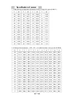
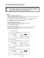
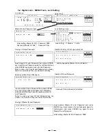
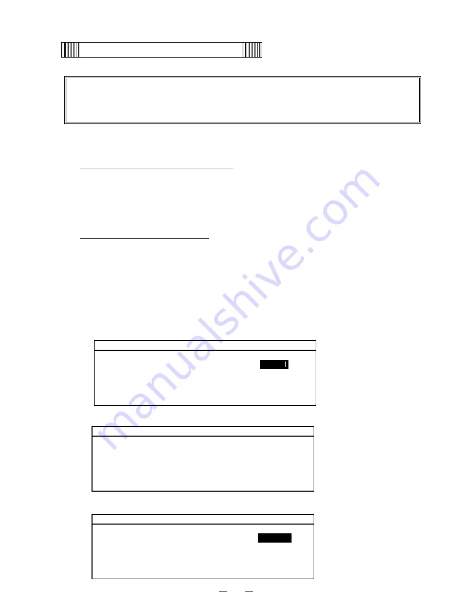
Operation of Control Panel
㩷
Note: For the operations of ‘Basic Screen’, ‘Function’, ‘Key Lock function’, ‘Display of Log’,
‘Various Setting’, ‘Initialization’ ‘Setting of date, time, log interval’ and ‘Key Lock
Password’, please refer to P.15~P.22 in the Instruction Manual.
0
1
0
2
1
1
1
2
1
3
1
4
1
5
1
6
1
7
1
8
1
9
2
0
2
1
2
2
2
3
2
4
2
5
2
6
2
7
2
8
2
9
3
0
3
1
3
2
3
3
3
4
3
5
3
6
3
7
3
8
3
9
4
0
1
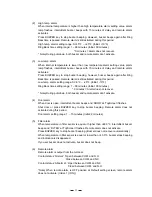
T o p S c r e e n
2
T e m p - 1 5 0
o
C
3
A l a r m
䋺
F i l t e r
4
S t a t u s
䋺
S t a n d - b y
5
D o o r
䋺
C l o s e d
P l e a s e c h e c k a c o n d e n s e r f i l t e r .
6
2 0 0 6 / 0 7 / 0 1 1 2 : 0 0 : 0 0
−150
℃
・
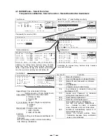
Buzzer for Temperature Alarm (Intermittent tone)
Buzzer beeps intermittently after 15 minutes has passed since the unit was detected High Temp. alarm or
Low Temp. alarm. Press BUZZER key to stop buzzer beeping.
Buzzer beeps again if the unit still keeps alarming condition even after Ring Back time has passed.
z
Intermittent buzzer tone and message indication emitted even after Auto Recovery.
z
Press BUZZER key to erase message and buzzer tone.
・
Buzzer for Door Alarm (Intermittent tone)
Buzzer beeps intermittently after delay time has passed since door was open.
Shut door or press BUZZER key to stop buzzer beeping.
z
Remote alarm does not activate.
・
Buzzer for Filter Alarm (Intermittent tone)
Buzzer beeps intermittently when temperature in filter sensor is equal or higher than +48.0
℃
Buzzer stops beeping when temperature in filter sensor is equal or lower than +43.0
℃
.
z
Remote alarm does not activate.
1
䋮
Buzzer
0
1
0
2
1
1
1
2
1
3
1
4
1
5
1
6
1
7
1
8
1
9
2
0
2
1
2
2
2
3
2
4
2
5
2
6
2
7
2
8
2
9
3
0
3
1
3
2
3
3
3
4
3
5
3
6
3
7
3
8
3
9
4
0
1
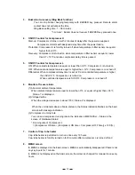
T o p S c r e e n
2
T e m p - 1 5 0
o
C
3
A l a r m
䋺
A l a r m
4
S t a t u s
䋺
S t a n d - b y
5
D o o r
䋺
C l o s e d
H i g h T e m p Wa r n i n g 2 0 0 6 / 0 7 / 0 1
0 3
䋺
1 5
䋺
3 0
6
2 0 0 6 / 0 7 / 0 1 1 2 : 0 0 : 0 0
−150
℃
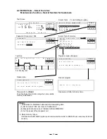
Screen of High Temp. alarm
0
1
0
2
1
1
1
2
1
3
1
4
1
5
1
6
1
7
1
8
1
9
2
0
2
1
2
2
2
3
2
4
2
5
2
6
2
7
2
8
2
9
3
0
3
1
3
2
3
3
3
4
3
5
3
6
3
7
3
8
3
9
4
0
1
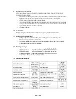
T o p S c r e e n
2
T e m p - 1 5 0
o
C
3
A l a r m
䋺
N o r ma l
4
S t a t u s
䋺
S t a n d - b y
5
D o o r
䋺
C l o s e d
P o w e r f a i l u r e Wa r n i n g 2 0 0 6 / 0 7 / 0 1 0 3
䋺
1 5
䋺
3 0
6
2 0 0 6 / 0 7 / 0 1 1 2 : 0 0 : 0 0
−150
℃
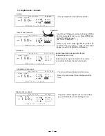
Screen of power failure
Screen of filter alarm
Summary of Contents for MDF-C2156VAN
Page 9: ...6 Dimensions ...
Page 11: ...8 Refrigeration circuits ...
Page 12: ...9 Refrigeration circuit welding points 䌅䌁㩷 䌅䌂㩷 䌅䌃㩷 䌅䌄㩷 䌅䌆㩷 䌅䌇㩷 Pipe layout ...
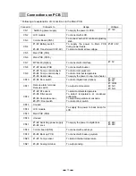
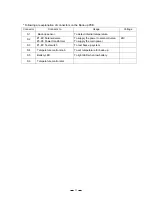
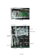
Page 14: ...11 Components on PCB ...
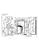
Page 19: ...16 Wiring Diagram MDF C2156VAN ...
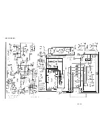
Page 20: ...17 MDF C2156VANC ...
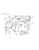
Page 21: ...18 Circuit Diagram ...
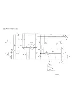
Page 22: ...19 CR Circuit Diagram ...