


25
9.
Operation in power failure
Unit checks power failure by the port for detecting power failure in every 0.42 seconds.
Operation in power failure;
-
All ports for controlling compressor, cap. tube heater, LCD back lamp, signal lines and
digital lock turn off and unit operates to the mode in low power consumption.
-
LCD is turned off and intermittent buzzer beeps.
-
If you press BUZZER key, buzzer stops beeping, LCD back lamp is lit for 5 seconds
and you can check the time when power failure was occurred. However, buzzer beeps
again after buzzer resume time is passed.
-
Log data is stored.
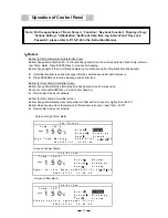
10. Auto
Return
Display changes to the basic screen if there are any key inputs for 90 seconds.
11. Notice of parts replacement
-
Battery replacement: When battery accumulating time is over than 2.8 years,
‘Please exchange batteries’ is indicated.
-
Fan motor replacement: When fan motor accumulating time is over than 5.6 years,
‘Please exchange fan motor’ is indicated.
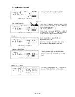
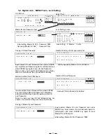
12. Warning
message
Y M D H M S
-
High temp. alarm: ‘ High Temp Warning 20XX/XX/XX XX:XX:XX ‘
-
Low temp. alarm: ‘ Low Temp Warning 20XX/XX/XX XX:XX:XX ‘
-
Power failure alarm: ‘ Power failure Warning 20XX/XX/XX XX:XX:XX ‘
-
Filter alarm: ‘ Please check a condenser filter ‘
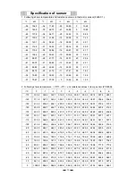
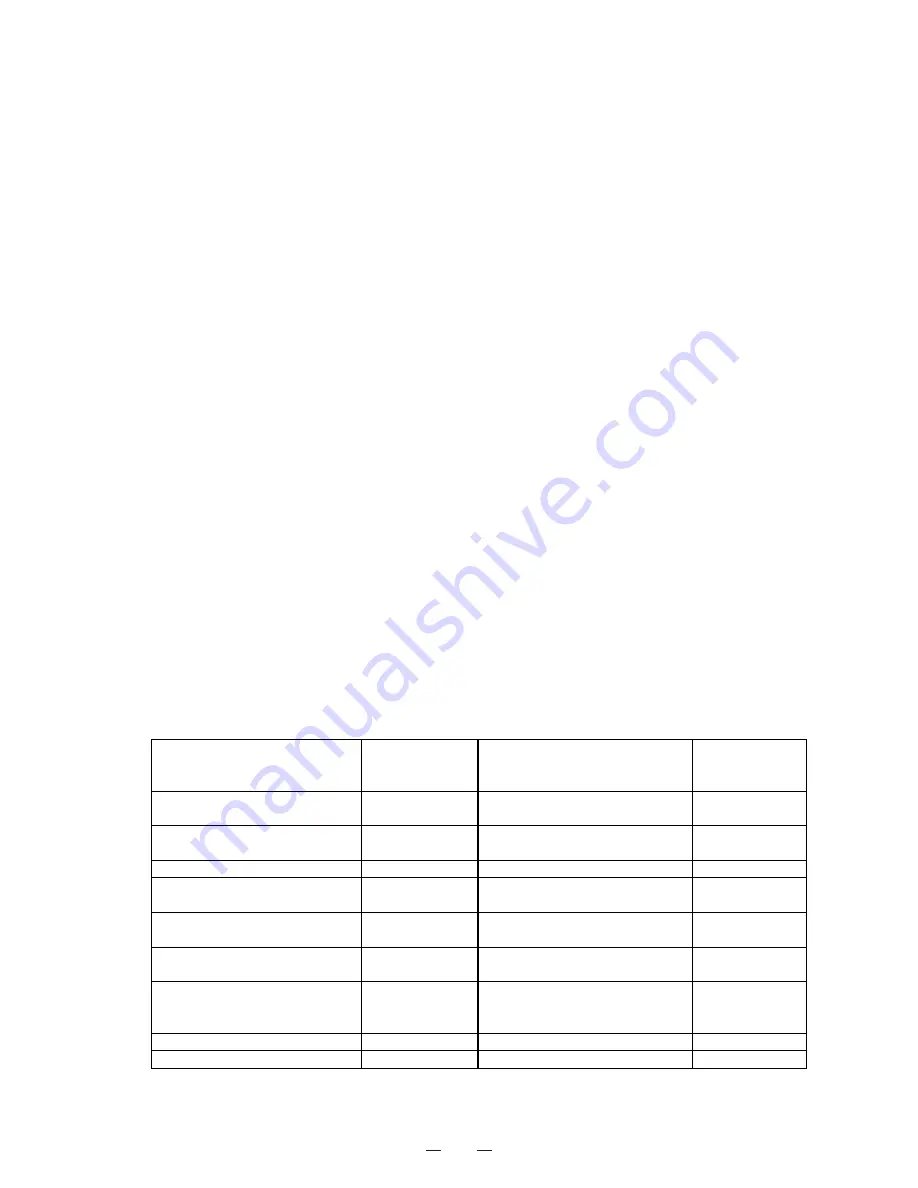
13. Setting
specifications
Internal temperature
-155
㷄
~-125
㷄
(Initial: -150
㷄
)
Ring Back
1~99 min.
0: OFF
(Initial: 30 min.)
High temp. alarm
+5
㷄
~+20
㷄
(Initial: +10
㷄
)
Door delay time
1~15 min.
(Initial: 2 min.)
Low temp. alarm
-5
㷄
~-20
㷄
(Initial: -10
㷄
)
Log record time
2~30 min.
(Initial: 15 min.)
Alarm delay time
15 min.
Compressor L delay time
2 min.
Compressor L ON/OFF
ON: -34
㷄
OFF: -12
㷄
Compressor delay time after
power failure
2~15 min.
(Initial: 15 min.)
Cycle of Cap. tube heater ON
Every 18hrs.
Cap. tube heater ON time
6~15 min.
(Initial: 8 min.)
Differential of Compressor L
+/- 0.5
㷄
Compressor
H
protection
OFF: +60
㷄
up
ON: AT+10
㷄
Filter alarm operation
Message
Buzzer:ON/OFF
(Initial: ON)
Internal temp. offset
-4.0
㷄
Auto Return
90 sec.
Auto MENU OFF
60 sec.
Key lock password
Initial: 0000
Summary of Contents for MDF-C2156VAN
Page 9: ...6 Dimensions ...
Page 11: ...8 Refrigeration circuits ...
Page 12: ...9 Refrigeration circuit welding points 䌅䌁㩷 䌅䌂㩷 䌅䌃㩷 䌅䌄㩷 䌅䌆㩷 䌅䌇㩷 Pipe layout ...
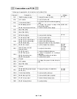
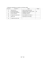
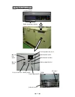
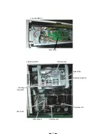
Page 14: ...11 Components on PCB ...
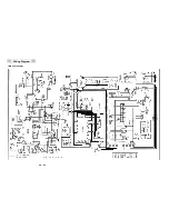
Page 19: ...16 Wiring Diagram MDF C2156VAN ...
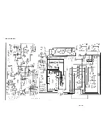
Page 20: ...17 MDF C2156VANC ...
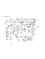
Page 21: ...18 Circuit Diagram ...
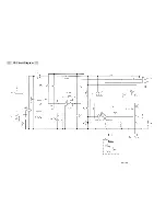
Page 22: ...19 CR Circuit Diagram ...