background image

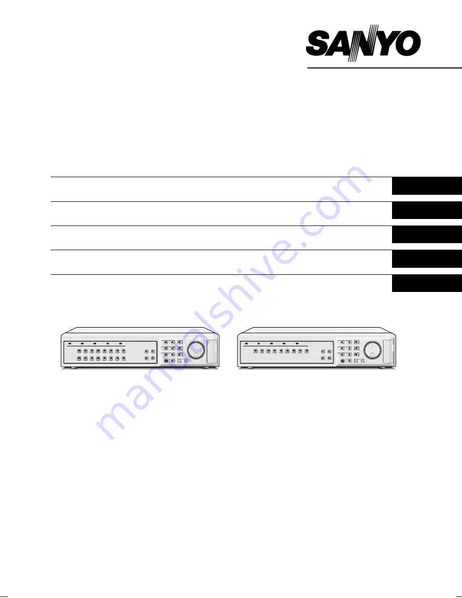
Digital Video Recorder
with Multiplexer Function

DSR-3016P
DSR-3009P

DSR-3016P

DSR-3009P

Instruction Manual

English

GB 

Bedienungsanleitung

Deutsch

Manuel d’instructions

Français

Manual de Instrucciones

Español

Manuale di Istruzioni

Italiano


About this manual

Before installing and using this unit, please read this manual
carefully. Be sure to keep it handy for later reference.

This manual gives basic connections and operating
instructions for 2 models.

Über diese Anleitung

Lesen Sie bitte diese Bedienungsanleitung vor der
Installation und der Verwendung des Gerätes sorgfältig
durch. Bewahren Sie die Anleitung zum späteren
Nachschlagen auf.

In dieser Anleitung werden die Anschlüsse und die
Bedienungsanleitungen für 2 Modelle beschrieben.

À propos de ce manuel

Avant d’installer et d’utiliser cet appareil, veuillez lire ce
manuel attentivement. Assurez-vous de le garder à portée de
la main pour référence ultérieure.

Ce manuel couvre les instructions de branchement et
d’utilisation de base pour deux modèles.

Acerca de este manual

Antes de instalar y usar este aparato, lea detenidamente este
manual. Asegúrese de guardarlo a mano para futuras
referencias.

Este manual le indica las conexiones básicas y las
instrucciones de funcionamiento de dos modelos.

Nota su questo manuale

Leggere attentamente questo manuale prima di passare
all’installazione ed all’uso di questo apparecchio. Conservare
il manuale in un posto sicuro per riferimenti futuri.

Questo manuale contiene istruzioni per i principali
collegamenti ed il funzionamento di due modelli.

L8HBA/XE (DSR-3016, 3009 GB) 2002. 7. 9

Summary of Contents for DSR-3009P

Page 1: ...n die Anschlüsse und die Bedienungsanleitungen für 2 Modelle beschrieben À propos de ce manuel Avant d installer et d utiliser cet appareil veuillez lire ce manuel attentivement Assurez vous de le garder à portée de la main pour référence ultérieure Ce manuel couvre les instructions de branchement et d utilisation de base pour deux modèles Acerca de este manual Antes de instalar y usar este aparat...

Page 2: ...oid locations subject to strong vibrations Avoid moving the unit between cold and hot locations Do not place the unit directly on top of a monitor TV as this may cause playback or recording problems Avoiding Electrical Shock and Fire Do not handle the power cord with wet hands Do not pull on the power cord when disconnecting it from an AC wall outlet Grasp it by the plug If any liquid is spilled o...

Page 3: ...pying images to the hard disk archive area 36 B Copying images from the archive area to a CompactFlash card or microdrive 37 C Copying images from the archive area to a DDS DAT drive or CD R drive 39 MENU FLOW CHART AND MENU OPERATIONS 42 Menu Flow Chart 42 Basic menu screen operations 43 Operations while a sub menu screen is displayed 43 Entering numbers 43 INITIAL SET MENU 44 A LANGUAGE CLOCK SE...

Page 4: ...can be displayed when an alarm occurs Timer setting allows the following settings to be made for each camera The monitor mask function allows images from selected cameras to be covered by gray patterns during certain time periods Automatic switching of camera images selected by timer period Setting of automatic screen switching speed for each camera for four different daily time zones A monitor ma...

Page 5: ...rature changes of around 10 C in an hour If the digital video recorder is moved to a place with a large difference in temperature or a high level of humidity condensation may form If the digital video recorder is used with condensation inside it operating problems may occur Do not install the digital video recorder in places which are constantly vibrating such as vehicles or trains The hard disk a...

Page 6: ...y and the 4 screen display changes 1 4 5 8 9 12 13 16 each time the QUAD button is then pressed The indicator illuminates to match the 4 screen display For the DSR 3009P model the 4 screen display changes each time the QUAD button is pressed 1 4 5 8 9 3 8 Multiple display button and indicator MULTI This button lets you switch the display to a 16 screen display or 9 screen display while monitoring ...

Page 7: ...drive The indicator illuminates during copying If the button is pressed during recording or while the digital video recorder is stopped backups copying to DAT can be carried out N TIMER button and indicator When the button is pressed when recording is stopped the digital video recorder switches to timer recording standby mode and when the setting time is reached timer recording starts O PLAY STOP ...

Page 8: ... area space warning output C Ground M ALARM IN terminals 1 16 These terminals send alarm signals resulting from the operation of externally connected alarm switches to the ALARM OUT control terminal for output The DSR 3009P model has nine alarm input terminals N SENSOR ALARM OUT terminal 1 16 When a response is received from a motion sensor that has been set using the menu settings an alarm signal...

Page 9: ...RMINATE DIGITAL IN OUT MON2 MIC IN 2 3 4 5 6 7 8 11 12 13 14 15 16 CONTROL 10 9 TV monitor sold separately VIDEO IN connector TV monitor sold separately S VIDEO IN connector Computer DO NOT CONNECT TO PHONE LINE PC Card SLOT MIC IN AUDIO OUT AUDIO IN ALARMFULL C R1 R2 C FULL WARNINGOUT NONRECOUT ALARMRESET ALARMOUT CLOCKSETOUT REMOTE SVHS MAIN MONITOR A B RS485 RS232C OFF ALARM OUT ON RS485 ALL RE...

Page 10: ...UT LOOP OUT LOOP OUT IN OUT IN MIC IN IN EJECT PC Card SLOT AC IN RS232C A LA R M FU LL SW O U T W A R N IN G O U T FULL OUT IN ALARM OUT CLOCK ADJUST C C C NC C N O N R EC O U T ALARM IN ALARM RESET NC C C OFF ALL RESET RS485 TERMINATE B A ON C RS485 REMOTE SUB OUT OUT DIGITAL VIDEO AUDIO S VIDEO SUB IN IN OUT OUT LOOP OUT LOOP OUT IN OUT IN MIC IN IN EJECT PC Card SLOT Digital video recorder mai...

Page 11: ...l circuit is constructed as shown in the illustration and connected to the remote control input R1 and R2 terminals of the CONTROL connector the digital video recorder can be operated by remote control Contact LOW input The DSR 3009P model can control up to nine cameras AC IN ALARM IN NSOR RM OUT C 1 2 3 4 5 6 7 8 9 10 11 12 13 14 15 16 OFF ALARM FULL ON RS485 C R1 R2 C FULL WARNINGOUT NONRECOUT A...

Page 12: ...d can be recorded C Archive area This is the area for copying important images from the normal recording area and the alarm recording area The size of the archive area can be set to a maximum of 10 GB 12 5 of total capacity when using an 80 GB hard disk 6 of total capacity when using an 160 GB hard disk by changing the size of the normal recording area or the alarm recording area Archive area C No...

Page 13: ... 0 50 2553H 1808H 1356H 986H 748H 0 33 3829H 2712H 2034H 1479H 1122H 0 25 5106H 3616H 2712H 1972H 1496H 0 20 6382H 4521H 3390H 2466H 1870H 0 10 12765H 9042H 6781H 4932H 3741H 0 05 25531H 18084H 13563H 9864H 7483H 0 03 38296H 27126H 20345H 14796H 11224H The tables below are recording time tables provided for reference if the total capacity of the hard disk has been increased to 160 GB Contact the p...

Page 14: ...larm is received EA flashes to the left of the camera number When a motion sensor alarm is received SA flashes to the left of the camera number 4 Amount of recording area remaining REPEAT appears when overwriting is enabled Furthermore if overwriting has been disabled OVERWRITE OFF for the normal recording area and the alarm recording area the amount of space remaining appears as a percentage You ...

Page 15: ...be enlarged See page 15 If you press the camera select button while zooming the image will be easier to see due to the movement of the subject The following changes will occur if you press the camera select button repeatedly An image with little movement almost a still image Large subjects become clearer and moving subjects appear a little rough An image with large movement normal viewing The imag...

Page 16: ...return to zoom display To make the zoom frame reappear press and hold camera select button 2 again for 3 seconds or more 4 Move the zoom frame to the section of the image to be enlarged If you turn the jog dial clockwise the zoom frame will move to the right If you turn it counterclockwise the zoom frame will move to the left If you turn the shuttle dial clockwise the movement direction changes to...

Page 17: ...lect button For the DSR 3009P model a 4 screen display of images from cameras 1 4 5 8 or 9 3 will appear each time the button is pressed Plus screen viewing The plus screen allows you to display the images from each camera as a quarter screen display in the lower right corner of the split screen display In addition images being recorded can be played back in the same position 1 Press the PLUS butt...

Page 18: ...he plus screen Viewing automatically switching images The camera images are switched automatically in the order that has been set using the SEQUENCE settings See page 82 Automatically switching of the single screen images 1 Switch to single screen display and then press the camera select buttons to select the camera for automatic switching example 1 The camera select buttons for the cameras that w...

Page 19: ...once more to return to the 4 screen display Automatic switching will be canceled and 4 screen display will be restored Automatically switching of the plus screen image 1 Press the PLUS button The plus screen is displayed 2 Press the SEQUENCE button The camera images in the plus screen will be switched automatically 3 Press the SEQUENCE button once more to return to the plus screen Automatic switch...

Page 20: ...g Press the SEQUENCE button The camera images being displayed on monitor 2 will switch automatically To cancel automatic switching press the SEQUENCE button once more Displaying single screen alarm images on monitor 2 When an alarm is received the alarm images will be displayed on monitor 2 as single screen images Note If alarm images are being displayed on monitor 2 change the MON 2 DISPLAY setti...

Page 21: ... proceeds automatically default setting according to the following settings The settings can be changed between long period recording and high quality recording in five steps See page 55 Hard disk recording areas Normal recording area 80 Alarm recording area 19 Archive area 1 Picture quality EN Enhanced Recording speed 8 33 FPS 81H Note Playback is possible during recording When the PLAY STOP butt...

Page 22: ...tch off and timer recording stops 3 Timer recording starts when the timer setting time is reached REC appears in the operating display and the images being monitored are recorded in the normal recording area Recording onto the hard disk proceeds automatically default setting according to the following settings The settings can be changed between long period recording and high quality recording in ...

Page 23: ...rts Alarm images are recorded in the alarm recording area Furthermore the number of alarms in the operating display is increased by one each time an alarm occurs Note Normal recording and timer recording stop when an alarm occurs during normal recording or timer recording 3 Ending alarm recording After the end of the alarm duration period default setting 5 sec the REC and ALARM displays stop flash...

Page 24: ...ing to the following settings The settings can be changed between long period recording and high quality recording in five steps See page 59 Hard disk recording areas Normal recording area 80 Alarm recording area 19 Archive area 1 Picture quality EN Enhanced Recording speed 8 33 FPS 81H 3 When an alarm is received pre alarm recording stops automatically and the alarm images are recorded The PRE di...

Page 25: ...ge 25 Locking speed for fast forward rewind playback See page 25 Releasing speed lock Normal playback When playing back recordings for the first time The recorded images will be played back from the beginning When playing back for the second or subsequent time Playback will start from the point where the last playback session ended Starting point for first playback Ending point Starting point for ...

Page 26: ... If it is turned counterclockwise f appears in the operating display and rewind playback starts When you release the shuttle dial normal playback resumes 2 Changing the playback speed Fast forward slow playback 1 Turn the jog dial clockwise Fast forward playback starts and e appears in the operating display 2 Turn the jog dial counterclockwise Slow playback starts and hc appears in the operating d...

Page 27: ...l is turned quickly the frame feed speed also increases However if the speed is too fast the images will stop Play back the images at an appropriate speed ZOOM 01 01 EN 17 11 02 02 36 00 EN 17 11 02 02 36 00 01 EN 17 11 02 02 36 00 ZOOM 01 01 EN 17 11 02 02 36 10 EN 17 11 02 02 36 10 01 EN 17 11 02 02 36 10 STILL 01 01 EN 17 11 02 02 38 00 EN 17 11 02 02 38 00 01 EN 17 11 02 02 38 00 STILL 01 01 E...

Page 28: ...y units 1 4 5 8 9 12 13 16 each time the button is pressed To return to a single screen display press a camera select button For the DSR 3009P model a 4 screen display of images from cameras 1 4 5 8 or 9 3 will appear each time the button is pressed Playing back images as 13 screen or 6 screen displays plus screen 1 Press the PLUS button The display changes to show a 13 screen or 6 screen display ...

Page 29: ...ea Alarm recording area a Alarm search See page 29 Preview display Single screen display Alarm image search and playback a Alarm image thumbnail search See page 30 Single screen display Thumbnail display Alarm image thumbnail search and playback a Time date search See page 30 Single screen display Preview display Searching and playing back recorded images by date time a Archive area search See pag...

Page 30: ...h starts playback from the image that was recorded at the instant the alarm occurred so if you are viewing pre alarm images use the shuttle operations to carry out rewind playback Alarm search only plays back alarm images for a single event When playback of the event is complete playback stops If you would like to play back the next alarm press an ALARM button Alarm search 2 1 Press an ALARM butto...

Page 31: ...back starts Note You can also use the shuttle dial or jog dial to carry out operations such as pausing and fast forward playback Only the contents of each alarm can be played back in the same way as for alarm searching Use the ALARM buttons to play back previous and subsequent alarm recordings Time date search The recording date and time for images in the normal recording area normal recording and...

Page 32: ...osest to the selected time range is displayed 5 Use the jog dial to select VIEW and then turn the shuttle dial clockwise The preview image is displayed and played back in a single screen Note A single screen image can be displayed when date and time are entered and VIEW is selected even without displaying a preview You can also use the shuttle dial or jog dial to carry out operations such as pausi...

Page 33: ...back only those images Note Specify the camera number channel to detect only the images from that camera 1 Press the SEARCH button during recording or when the digital video recorder is stopped The SEARCH screen appears 2 Use the jog dial to select MOTION DETECTION SEARCH and then turn the shuttle dial clockwise The MOTION DETECTION SEARCH screen appears 3 Use the jog dial to select SEARCH FROM an...

Page 34: ...EVIEW The selected start point appears If you turn the shuttle dial clockwise you can check the images up until the end point 5 VIEW The selected image appears on the monitor as a single screen image in a normal screen 7 Turn the shuttle dial clockwise Use the jog dial to set the START date and time example 10 00 am on the current day for the motion sensor setting and then turn the shuttle dial cl...

Page 35: ...otion sensor settings have been made NOT FOUND appears so make sure that the motion sensor settings have been made correctly 11To view a motion sensor setting in a single screen display use the jog dial to move the cursor to VIEW and then turn the shuttle dial clockwise The display changes from the specified image to normal playback Note If the camera number has been specified as a channel when ca...

Page 36: ...02 36 00 Archive area Normal Normal recording area recording area Normal recording area Alarm Alarm recording recording area area Alarm recording area Hard disk Normal recording area Alarm recording area Normal recording area Alarm recording area Copying Copying 01 EN 17 11 02 02 36 00 01 01 EN 17 11 02 02 36 00 EN 17 11 02 02 36 00 01 EN 17 11 02 02 36 00 01 EN 17 11 02 02 36 00 CF card or microd...

Page 37: ...al clockwise The cursor moves to HOW MANY 5 Turn the shuttle dial clockwise use the jog dial to change the setting to 10 and then turn the shuttle dial clockwise 6 Use the jog dial to select the SECONDS setting and then turn the shuttle dial clockwise PICTURES Specify the number of images to be copied SECONDS Specify the number of seconds of images to be copied MINUTES Specify the number of minute...

Page 38: ...jog dial to select COPY TO and then turn the shuttle dial clockwise The ARCHIVE AREA display flashes 3 Use the jog dial to select COMPACIT FLASH and then turn the shuttle dial clockwise The cursor moves to HOW MANY 4 Turn the shuttle dial clockwise use the jog dial to change the setting to 10 and then turn the shuttle dial clockwise The cursor moves to PICTURES 1 2 3 2 1 3 Inserting Removing COPY ...

Page 39: ...cting FORMAT COMPACTFLASH The formatting is according to FAT16 specifications CompactFlash recording area 1 A SANYO folder is created in the root directory 2 Sub folders for holding the copied images are created in sequence in the SANYO folder 3 Sub folders are created within the date time folder with names starting from IMG00001 Each sub folder can hold 200 images 4 To view the file listing using...

Page 40: ...2 bit card bus types of card as they may damage the PC card slot of the digital video recorder DDS Digital Data Strage DAT Digital Audio Tape Backing up to a DDS DAT drive All of the data in the archive area can be backed up on a DDS DAT drive 1 Press the COPY button during recording or when the digital video recorder is stopped The ARCHIVE SET screen appears 2 Use the jog dial to select BACK UP a...

Page 41: ...he images in the archive area the image data that has been read can be played back Deleting DDS DAT drive image data 1 Press the COPY button during recording or when the digital video recorder is stopped The ARCHIVE SET screen appears 2 Use the jog dial to select ERASE and then turn the shuttle dial clockwise The WARNING screen appears 3 Use the jog dial to change NO to YES and then turn the shutt...

Page 42: ... the archive area can be copied to a CD R drive Images cannot be copied directly from the normal recording area or alarm recording area to a CD R Depending on the duration of each event it may not be possible to copy all of the events specified The maximum amount of data that can be copied is 650 MB In the case of the EVENTS setting if you select the 60 setting copying will continue until the CD R...

Page 43: ... SHUTTLE POWER FAILURE USED TIME POWER FAILURE 001 FAILURE 12 02 07 22 RECOVER 15 02 10 20 USED TIME DISK1 USE 00003H DISK2 USE H POWER 00358H FIRMWARE MAIN 1 10 00 SUB 1 01 00 The setting items in this menu relate to initial settings Sets the language and clock Sets the timer Sets holidays The setting items in this menu relate to image recording Sets the recording area Sets the recording conditio...

Page 44: ... RECORD SET 3 GENERAL SET 4 SCREEN SET 5 POWER FAILURE USED TIME 6 COPY MENU SETTINGS MOVE LINES WITH JOG SELECT WITH SHUTTLE INITIAL SET 1 LANGUAGE CLOCK SET 2 TIME PERIOD SET 3 HOLIDAY SET 4 CAMERA DETECT MOVE LINES WITH JOG SELECT WITH SHUTTLE EXIT OSD INITIAL SET 1 LANGUAGE CLOCK SET 2 TIME PERIOD SET 3 HOLIDAY SET 4 CAMERA DETECT MOVE LINES WITH JOG SELECT WITH SHUTTLE RECORD SET 1 RECORDING ...

Page 45: ...00 00 00 00 00 00 00 TIME PERIOD B 00 00 00 00 00 00 00 00 SELECT TIME PERIOD SEQUENCE TIME PERIOD A MASK TIME PERIOD A MOTION SENSOR TIME PERIOD A HOLIDAY SET 1 11 2 12 3 13 4 14 5 15 6 16 7 17 8 18 9 19 10 20 Sets the date and time that are normally displayed on the screen You should always enter the correct date and time If this is not set recording will not be possible The digital video record...

Page 46: ... flashes 2 Use the jog dial to set USE and then turn the shuttle dial clockwise The cursor moves to ON Display examples USE Summer time is used NO USE Summer time is not used 3 Turn the shuttle dial clockwise The cursor moves to the LST setting in the WEEK column 4 Turn the jog dial to select 1ST and then turn the shuttle dial clockwise The cursor moves to SUN 5 Turn the jog dial to select SUN and...

Page 47: ...d each timer setting can be made in four time zones example midnight morning daytime night For example TIME PERIOD A time zones can be set for automatic screen switching and TIME PERIOD B time zones can be set for gray pattern cover on camera images LANGUAGE LANGUE SPRACHE IDIOMA ENGLISH CLOCK SET 01 01 2002 TUE 00 00 00 SUMMER TIME SET MODE USE WEEK MONTH TIME ON LST SUN 03 02 00 OFF LST SUN 10 0...

Page 48: ...se 00 minutes flashes in the T1 column 5 Turn the jog dial to change the T1 setting to 00 minutes and then turn the shuttle dial clockwise 00 hour flashes in the T2 column 6 Turn the jog dial to change the T2 setting to 06 hour and then turn the shuttle dial clockwise 00 minutes flashes in the T2 column 7 Turn the jog dial to change the T2 setting to 30 minutes and then turn the shuttle dial clock...

Page 49: ... as a holiday 1 Press the MENU button to select INITIAL SET and then turn the shuttle dial clockwise The INITIAL SET sub menu appears and the cursor is positioned at LANGUAGE CLOCK SET 2 Use the jog dial to move the cursor to HOLIDAY SET and then turn the shuttle dial clockwise The HOLIDAY SET sub menu appears 3 Turn the shuttle dial clockwise day flashes in the line 1 4 Use the jog dial to change...

Page 50: ...rn the shuttle dial clockwise The INITIAL SET sub menu appears and the cursor moves to LANGUAGE CLOCK SET 2 Use the jog dial to move the cursor to CAMERA DETECT and then turn the shuttle dial clockwise All cameras that are connected to the digital video recorder are detected and the settings for any unconnected cameras are changed to OFF MENU INITIAL SET 1 LANGUAGE CLOCK SET 2 TIME PERIOD SET 3 HO...

Page 51: ...D SET 1 RECORDING AREA SET 2 RECORDING CONDITIONS SET 3 NORMAL REC MODE SET 4 PROGRAM REC SET 5 TIMER SET 6 ALARM REC MODE SET 7 ALARM OPERATION SET MOVE LINES WITH JOG SELECT WITH SHUTTLE Changes the alarm settings for detecting suspicious people and also changes motion sensor settings Changes the timer settings You must always set the timer when carrying out timer recording Changes the program r...

Page 52: ...MIRRORING of the HDD SET setting has been set to ON the TOTAL CAPACITY display of RECORDING AREA SET shows a smaller value for the hard disk capacity Resetting each recording area Example Set the normal recording area to 50 and the alarm recording area to 49 1 Press the MENU button to select RECORD SET and then turn the shuttle dial clockwise The RECORD SET sub menu appears and the cursor moves to...

Page 53: ...n Note For overwriting to be carried out automatically change the OVERWRITE setting for the NORMAL RECORDING AREA or ALARM RECORDING AREA to ON B RECORDING CONDITIONS SET menu This describe how to make settings for recording Recording settings for digital series connection maximum 2 units besides this unit 1 Connect the digital video recorders using the digital input and output terminals of each d...

Page 54: ...rom the earliest recorded images Note If OFF is selected the REMAINING DISK WARNING setting shows the percentage of hard disk space remaining that triggers the FULL or ALARM FULL indicator on the front panel to start flashing 3 Follow the same procedure to make the setting OFF for the ALARM RECORDING AREA Note Make the settings separately for each item in the menu even if making a digital connecti...

Page 55: ...8 33FPS to 50FPS When set to ON the letter A audio recording indicator appears in front of the REC RATE recording rate This is because the audio recordings are also made in the normal recording area so that the image recording capacity of the normal recording area is reduced 6 Turn the shuttle dial clockwise use the jog dial to set the recording speed example 0 1 and then turn the shuttle dial The...

Page 56: ...mple P 1 and then turn the shuttle dial clockwise The cursor moves to 01 4 Turn the shuttle dial clockwise 0 313 camera number flashes 5 Turn the shuttle dial clockwise use the jog dial to set the recording speed example 0 521 and then turn the shuttle dial clockwise Camera 1 will record at a speed of 0 521 The cursor then moves to 02 6 Repeat the above procedure to set the recording speeds for ca...

Page 57: ...ECORD SET and then turn the shuttle dial clockwise The RECORD SET sub menu appears and the cursor moves to RECORDING AREA SET 2 Use the jog dial to move the cursor to TIMER SET and then turn the shuttle dial clockwise The TIMER SET sub menu appears and the cursor is positioned at SUN 3 Turn the shuttle dial clockwise SUN flashes in the WEEK column 4 Use the jog dial to change from SUN to DLY and t...

Page 58: ...on Wednesday 1 Use the jog dial to move the cursor to the 7th line SAT and then turn the shuttle dial SAT flashes in the WEEK column 2 Use the jog dial to change from SAT to MON and then turn the shuttle dial clockwise hours flashes in the START column Note This can also be set using the numeric keys See page 43 3 Use the jog dial to change from to 10 and then turn the shuttle dial clockwise minut...

Page 59: ...turn the shuttle dial clockwise 25 flashes in the FPS column 10Use the jog dial to set the recording cycle to 16 67 and then turn the shuttle dial clockwise OFF flashes in the SET column 11Use the jog dial to change from OFF to ON and then turn the shuttle dial clockwise The cursor moves to the first line 12Press the EXIT OSD button The display returns to the normal screen WED 20 30 OFF 25FPS OFF ...

Page 60: ...NTERLEAVE ONLY PROGRAM GROUP OFF ALARM REC MODE SET PICTURE QUALITY ENHANCED AUDIO RECORDING ON ALARM RECORDING ENABLED ALARM INTERLEAVE ONLY PROGRAM GROUP OFF REC RATE 25FPS DURATION 5SEC PRE ALARM RECORDING ON REC RATE FPS DURATION 07733 ALARMS CAN BE RECORDED ALARM TRIGGER ALARM Alarm canceled Alarm Alarm Alarm ONLY SW Recording continues until alarm is canceled Multiple alarm recording images ...

Page 61: ...se the jog dial to set the recording speed example 8 33 and then turn the shuttle dial clockwise DURATION of 5SEC flashes Note When the recording speed is selected the maximum number of recordings appears underneath it at the bottom of the screen 20480 ALARMS CAN BE RECORDED 9 Use the jog dial to set the recording time duration example 5 and then turn the shuttle dial The cursor moves to PRE ALARM...

Page 62: ... 2 and 4 B ONLY Only images from the camera where the alarm is detected are recorded If more than one alarm has been detected the alarm images are recorded alternately Recording pattern if an alarm occurs at camera 2 Recording pattern if alarms occur at two or more cameras example cameras 2 and 4 Camera 2 alarm Alarm canceled Alarm camera images and images from all cameras are recorded alternately...

Page 63: ...hen pre alarm recording has been set the pre alarm recording speed and the recording speed for normal recording will be fixed at 15 FPS A warning screen appears to verify confirm this so select YES 8 Press the EXIT OSD button The display returns to the normal screen PRE appears in the operating display section When an alarm is triggered the display switches to ALARM Note Pre alarm recording contin...

Page 64: ... SENSOR settings must be made if SENSOR ALARM AND SENSOR or ALARM OR SENSOR is selected The digital video recorder s built in motion sensor cannot be used if a multiplexer is connected to the digital video recorder If using the built in sensor of a multiplexer the alarm output should be directed to the alarm input of the digital video recorder in order to record alarms If you stop recording while ...

Page 65: ...the main monitor Changes the settings for recording double alarms Allows alarm recording images to be displayed on monitor 2 Changes the RETRIGGER setting INITIAL SET 1 LANGUAGE CLOCK SET 2 TIME PERIOD SET 3 HOLIDAY SET 4 CAMERA DETECT MOVE LINES WITH JOG SELECT WITH SHUTTLE TIME PERIOD SET TIME PERIOD T1 T2 T3 T4 TIME PERIOD A 00 00 00 00 00 00 00 00 TIME PERIOD B 00 00 00 00 00 00 00 00 SELECT T...

Page 66: ...ction alarm In the case of a camera signal being suddenly interrupted due to an accident etc a setting can be made to record the image immediately prior to the interruption a still image or a test pattern When an alarm occurs the indicator on the camera select button for the camera that produced the alarm example 4 will start flashing When an alarm occurs the screen changes to a still image or a t...

Page 67: ...etected at the same time only the first alarm received is displayed and images for subsequent alarms are not displayed SWITCH When more than one alarm is detected at the same time the alarm images for each alarm are displayed alternately at 1 second intervals 6 Use the jog dial to select the MON 2 DISPLAY setting example OFF and then turn the shuttle dial clockwise The cursor moves to RETRIGGER Di...

Page 68: ...riggered if there is any change in the movement of a subject passing from point A to point B C A motion sensor alarm is generated when the whole screen area changes uniformly This results in a reaction at times such as when the camera is sprayed with something Sensor settings are not required 7 EXIT When this is selected the display returns to the previous screen 1 After changing the TIMER A and T...

Page 69: ... 1 Press the MENU button to select RECORD SET and then turn the shuttle dial clockwise The RECORD SET sub menu appears and the cursor is positioned at RECORDING AREA SET 2 Use the jog dial to move the cursor to ALARM OPERATION SET and then turn the shuttle dial clockwise The ALARM OPERATION SET sub menu appears and the cursor is positioned at MAIN MON DISPLAY 3 Use the jog dial to move the cursor ...

Page 70: ...arm will then be canceled When images from the camera where the alarm was detected are displayed in a multiple screen 1 Press the camera select button for the camera that is showing the alarm The alarm images will appear in a single screen display 2 Press the camera select button again for approximately 3 seconds The alarm will then be canceled Note Alarms can also be reset by using the ALARM RESE...

Page 71: ...S 232C RS 485 SET 5 HDD SET 6 NETWORK SET MOVE LINES WITH JOG SELECT WITH SHUTTLE These settings relate to buzzer operation A buzzer can be made to sound when an alarm is detected or a hard disk problem occurs Displays settings such as the date and time and the image quality on the monitor In addition the number of alarms and types of alarm can also be displayed Sets titles Changes the video loss ...

Page 72: ...ARM COUNT OFF The current number of alarms does not appear ALARM TYPE OFF The type of alarm recording does not appear TITLE OFF The camera title does not appear Note If ALARM RECORDING in the ALARM REC MODE SET menu has been set to OFF ALARM COUNT and ALARM TYPE do not appear When set to ON ALARM appears in the operating display during alarm recording PRE appears in the operating display during pr...

Page 73: ...The color level can be adjusted manually in 10 steps B BUZZER SET setting The buzzer can be made to sound as a warning during an alarm and when the hard disk becomes full 1 Press the MENU button to select GENERAL SET and then turn the shuttle dial clockwise The GENERAL SET sub menu appears and the cursor is positioned at DISPLAY SET 2 Use the jog dial to move the cursor to BUZZER SET and then turn...

Page 74: ... be set The password can consist of between four and eight alphanumeric characters 3 Turn the shuttle dial clockwise The first password entry bar flashes 4 Use the jog dial to display 1 and then turn the shuttle dial The second password entry bar flashes The characters that can be used in the password are 0 1 9 A B C Z Note This can also be set using the numeric keys See page 43 5 Use the jog dial...

Page 75: ... are locked When the user password is entered at the password entry screen only playback and recording operations can be carried out When the Administrator password is entered all operations can be carried out Recording and menu operations are locked Playback operations are not locked When the Administrator password is entered all operations can be carried out Menu operation is locked Recording an...

Page 76: ...lect CONTROL and then turn the shuttle dial clockwise RS 232C flashes Use the jog dial to select either RS 232C or RS 485 RS 232C Selection For connection of the RS 232C terminal of the digital video recorder to a computer please use a special RS 232C cable sold separately See page 7 1 Turn the jog dial to select RS 232C and then turn the shuttle dial clockwise The cursor moves to DATA SPEED 2 Tur...

Page 77: ... clockwise This completes the setting and the cursor moves to CONTROL Note The range of valid addresses for this unit is from 0 to 127 If more than one digital video recorder is connected be careful that same addresses are not repeated Address item 0 to 127 6 Press the EXIT OSD button The display returns to the normal screen E HDD SET setting This displays the hard disk capacity for disk 1 standar...

Page 78: ...n error has occurred in the playback image switch from the hard disk in current use DISK1 to DISK2 F NETWORK SET SETTING Network connection Insert a recommended commercially available LAN card or PC card Ethernet card into the PC card slot at the rear of the digital video recorder This will enable you to view images on this unit and make menu settings through the network LAN from a personal comput...

Page 79: ...ROL cannot be set to ON 6 Turn the shuttle dial clockwise and use the jog dial and shuttle dial to display the IP ADDRESS example 192 168 0 1 and then turn the shuttle dial clockwise With the final shuttle dial movement the cursor moves to SUBNET MASK 7 Turn the shuttle dial clockwise and use the jog dial and shuttle dial to display the SUBNET MASK example 255 255 255 0 and then turn the shuttle d...

Page 80: ...operations and settings to be carried out 2 Use the jog dial to display A and then turn the shuttle dial The second digit 1 flashes 3 Use the jog dial to display B and then turn the shuttle dial The third digit 1 flashes 4 Repeat this procedure to continue entering 123456 and then turn the shuttle dial clockwise The cursor moves to ID2 5 As required use the same procedure to set passwords for ID2 ...

Page 81: ... the monitor See page 85 When the timer function has been set you can hide the camera images with a gray pattern at intervals corresponding to the setting time Split screen display position setting See page 81 A Automatic switching time setting See page 82 B Mask setting See page 85 C You can switch all camera images after the set time interval Select the cameras that you do not want to be display...

Page 82: ...ise 01 flashes 5 Use the jog dial to move the cursor to camera number 06 and then turn the shuttle dial clockwise 06 flashes Note This can also be set using the numeric keys See page 43 6 Use the jog dial to set 01 and then turn the shuttle dial clockwise 06 changes to 01 7 Repeat steps 4 and 5 above to set 11 and 16 to 01 11 and 16 change to 01 Note If you select CHECK THE SCREEN at the bottom of...

Page 83: ...tting This lets you set the automatic switching time The switching time setting for automatic switching display is only effective for single screen and 4 screen displays Two types of setting can be made all cameras can be switched at the same time or the switching times can be set separately for each camera Example 1 To set 5 second intervals for automatic switching display of all main and spot mo...

Page 84: ...hen turn the shuttle dial clockwise 1S flashes 5 Use the jog dial to set INDIV and then turn the shuttle dial clockwise 6 Use the jog dial to move the cursor to INDIVIDUAL INTERVAL SET and then turn the shuttle dial clockwise The INDIVIDUAL INTERVAL SET sub menu appears 7 Use the jog dial to move the cursor to CAMERA 1 01 and then turn the shuttle dial clockwise 1S flashes 8 Use the jog dial to se...

Page 85: ...R SET sub menu will be displayed This sub menu screen is used to select whether the images from cameras 1 to 16 are displayed or not displayed for the time set by the timer setting T 1 8 Turn the shuttle dial clockwise use the jog dial to select T 1 and then turn the shuttle dial clockwise The cursor moves to 01 9 Use the jog dial to move the cursor to CAMERA 1 01 and then turn the shuttle dial cl...

Page 86: ... hide the images for individual cameras with a gray pattern The DSR 3009P model can display only cameras 01 to 09 Example 1 To prevent certain camera images from being monitored for the period of time set by the timer TIMER A B 1 Set the timer setting for both TIMER A and TIMER B in the TIME PERIOD SET menu See page 46 Set both TIMER A and TIMER B MAIN MONITOR SET T 1 MAIN MONITOR SET T 2 MAIN MON...

Page 87: ...witch between T 1 T 2 T 3 and T 4 10Use the jog dial to move the cursor to 01 and then turn the shuttle dial clockwise OFF flashes 11Use the jog dial to set ON and then turn the shuttle dial clockwise Repeat the above procedure to set cameras 3 03 5 05 7 07 and 9 09 to ON Note Repeat steps 10 to 12 to set T 3 and T 4 as required 12Press the EXIT OSD button The display will return to the normal scr...

Page 88: ...e time when power was restored 3 DISK1 USE Shows the total hard disk 1 usage time 4 DISK2 USE Shows the total hard disk 2 usage time when a hard disk has been added 5 POWER Shows the total usage time for this unit MAIN MENU 1 INITIAL SET 2 RECORD SET 3 GENERAL SET 4 SCREEN SET 5 POWER FAILURE USED TIME 6 COPY MENU SETTINGS MOVE LINES WITH JOG SELECT WITH SHUTTLE POWER FAILURE USED TIME POWER FAILU...

Page 89: ...MENUS TO CF and then turn the shuttle dial clockwise The WARNING screen will appear to let you confirm the saving 2 To save the settings use the jog dial to display YES and then turn the shuttle dial clockwise Saving will then start When saving is complete SAVING FINISHED will be displayed A file called MENUCOPY TXT will be created in the CompactFlash card directory MENU 1 2 COPY MENU SETTINGS DVR...

Page 90: ...huttle dial clockwise Loading will then start When saving is complete LOADING FINISHED will be displayed If copying the recording area settings This describes how to copy the recording area settings Normally you should set COPY RECORDING AREA SETTINGS to NO 1 To copy the settings use the jog dial to set COPY RECORDING AREA SETTINGS to YES and turn the jog dial to select LOAD MENUS FROM CF and then...

Page 91: ... 0 087 1 250 0 625 0 417 0 313 0 250 0 208 0 179 0 156 0 139 0 125 0 114 0 104 0 096 0 089 0 083 0 078 1 136 0 568 0 379 0 284 0 227 0 189 0 162 0 142 0 126 0 114 0 103 0 095 0 087 0 081 0 076 0 071 1 042 0 521 0 347 0 260 0 208 0 174 0 149 0 130 0 116 0 104 0 095 0 087 0 080 0 074 0 069 0 065 0 962 0 481 0 321 0 240 0 192 0 160 0 137 0 120 0 107 0 096 0 087 0 080 0 074 0 069 0 064 0 060 Unit FPS ...

Page 92: ...peed 2400 4800 9600 19200 bps Parity None Stop bit 1 Communication protocol A proprietary Sanyo protocol SSP Security Serial Protocol is used It is recommended that a special controller be used Contact the place of purchase for further details on obtaining a special controller RS485 termination switch settings RS485 TERMINATE Termination setting If several unit are being connected together termina...

Page 93: ...ER ON OFF 1 2 3 SHIFT SHIFT 4 SHIFT SHIFT MENU 5 SHIFT RP UP 6 SHIFT RP DOWN 7 8 9 SECURITY LOCK ON A ACK PLAY REV PLAY SEARCH DVR B NAK C GROUP SET D GROUP CHECK E GROUP CLEAR F STOP STILL Upper bit 8 9 A B C D E F Lower bit 0 CLOCK ADJUST 1 MENU RESET 2 3 4 5 ZOOM MPX 6 7 STATUS SENSE 8 MENU UPLOAD MENU DOWNLOAD 9 CLOCK DOWNLOAD A REC REC DUB REQUEST B FF ALARM F C CHANNEL REW ALARM R D COPY RS ...

Page 94: ...P S Video output terminal Separate YC signals DIN connector x 1 Digital output terminal RJ 45 x1 Audio output terminal 8dBs 600 Ω unbalanced RCA pin jack Compact Flash Slot Compact Flash Type 2 Front PC Card Slot PCMCIA Type 2 Rear for SCSI or Ethernet card RS 232C terminal D SUB 9pin for PC Control connectors RS 485 terminal DJ 11 3 terminals A B C GND Remote control input terminal External switc...

Page 95: ... 1AC6P1P2521 A L8HBA XE XE2 UK UK2 L8HBB XE XE2 UK UK2 0702KP CZ Printed in Japan Printed on recycled paper Gedruckt auf recyceltem Papier Imprimé sur du papier recyclé Impreso en papel reciclado Stampato su carta riciclata ...

Reviews: