background image

— 2 —

SAFETY PRECAUTIONS

WARNING: The chassis of this receiver has a floating
ground with the potential of one half the AC line voltage in
respect to earth ground. Service should not be attempted by
anyone not familiar with the precautions necessary when
working on this type of equipment. 

The following precautions must be observed:

1. An isolation transformer must be connected in the power

line between the receiver and the AC line before any ser-
vice is performed on the receiver.

2. Comply with all caution and safety-related notes provid-

ed on the side of the cabinet, inside the cabinet, on the
chassis, and the picture tube.

3. When replacing a chassis in the cabinet, always be certain

that all the protective devices are installed properly, such
as control knobs, adjustment covers, shields and barriers.

DO NOT OPERATE THIS TELEVISION RECEIVER 
WITHOUT THE PROTECTIVE SHIELD IN POSITION AND
PROPERLY SECURED.

4. Before replacing the back cover of the set, thoroughly

inspect the inside of the cabinet to see that no stray parts
or tools have been left inside.
Before returning any television to the customer, the 
service technician must perform the following safety
checks to be sure that the unit is completely safe to 
operate without danger of electrical shock.

ANTENNA COLD CHECK

Remove AC plug from the 120 VAC outlet and place a
jumper across the two blades. Connect one lead of an ohm-
meter to the jumpered AC plug, and touch the other lead to
each exposed antenna terminal (UHF and VHF antenna ter-
minals). The resistance must measure between 1M ohm and
5.2M ohm. Any resistance value below or above this range
indicates an abnormality which requires corrective action.

LEAKAGE CURRENT CHECK

Plug the AC line cord directly into a 120 VAC outlet. (Do not
use an isolation transformer for this check.) Use an AC volt-
meter, that has 5000 ohms per volt or more sensitivity.
Connect a 1500 ohm 10 watt resistor, paralleled by a 0.15 µF
150 VAC capacitor, between a known good earth ground
(water pipe, conduit, etc.) and all exposed metal parts of the
cabinet (antennas, handle bracket, metal cabinet, screw
heads, metal overlays, control shafts, etc.). Measure the AC
voltage across the 1500 ohm resistor. The AC voltage
should not exceed 750 mV. A reading exceeding 750 mV
indicates that a dangerous potential exists. The fault must
be located and corrected. Repeat the above test with the
receiver power plug reversed.

NEVER RETURN A RECEIVER TO THE CUSTOMER 
WITHOUT TAKING THE NECESSARY CORRECTIVE ACTION.

X-RADIATION PRECAUTION

The primary source of X-RADIATION in solid-state receivers is
the picture tube. The picture tube is specially constructed to
limit X-Ray emission. For continued X-RADIATION protection,
the replacement tube must be the same type as the original
(including the suffix letter in the part numbers). Excessive high
voltage may produce potentially hazardous X-RADIATION. To
avoid such hazards, the high voltage must be maintained within
specific limits. Refer to the X-RADIATION WARNING NOTE on
the CHASSIS SCHEMATIC in this service manual for specific
high voltage limits. If the high voltage exceeds specified limits,
check the components specified on the chassis schematic
diagram and take the necessary corrective action. Carefully
follow the instructions for the +B Voltage Check and the High
Voltage Check to maintain the high voltage within the specified
limits.

HIGH VOLTAGE  HOLD-DOWN TEST

To prevent X-RADIATION from the picture tube due to
excessive high voltage, a HOLD-DOWN circuit is provided in
the high voltage circuit. Every time the receiver is serviced,
the high voltage HOLD-DOWN circuit must be tested for
proper operation. Refer to the HIGH VOLTAGE HOLD-
DOWN TEST in service adjustments.

PRODUCT SAFETY NOTICE

When replacing components in a receiver, always keep in
mind the necessary product safety precautions. Pay special
attention to the replacement of components marked with a
star (

) in the parts list and in the schematic diagrams. To

ensure safe product operation, it is necessary to replace
those components with the exact same PARTS.

SAFETY INSTRUCTIONS

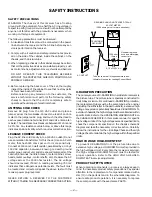
0.15 

µ

F 150V AC

1500 ohm

10 watt

Good earth ground
such as a water pipe,
conduit, etc.

AC OUTLET

TELEVISION

RECEIVER

READING SHOULD NOT EXCEED 750 mV.

AC VOLTMETER

(5000 ohms per volt or more sensitivity)

To be touched to all of exposed metal parts.
Voltmeter Hook-up for Leakage Current Check.

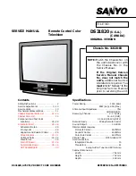
Summary of Contents for DS31820

Page 1: ...tional Service Literature is required You must refer to Notices to the Original Service Manual prior to servicing the unit G7TPA PRODUCT CODE 111370488 REFERENCE No SS780048 THIS CHASSIS IS SIMILAR TO MODEL DS31820 CHASSIS NUMBER 31820 00 SERVICE INFORMATION GIVEN IN THIS MANUAL IS ONLY THE DIFFERENCE INFORMATION FROM MODEL DS31820 CHASSIS NUMBER 31820 00 FOR ADDITIONAL SERVICE INFORMATION REFER T...

Page 2: ... 312 5008 SANYO BADGE 610 299 9600 OWNER S MANUAL 610 312 0942 OWNER S MANUAL 645 052 5018 RC TRANSMITTER 645 058 8150 RC TRANSMITTER DIFFERENCES MODEL DS32224 Chassis No 32224 00 SAME AS MODEL DS31820 Chassis No 31820 00 EXCEPT 1 IN THE CABINET ACCESSORY PARTS LIST MODEL DS31820 Chassis No 31820 00 MODEL DS32224 Chassis No 32224 00 Part No Description KEY NO Part No Description MENU VOL POWER CH ...

Page 3: ...12 2571 ASSY PWB CRT A1000 610 300 2132 ASSY PWB AV 610 312 2588 ASSY PWB AV Q901 414 010 6905 CRT M78JUA361X72 414 010 7001 CRT M80JUA068X72 2 IN THE CHASSIS ELECTRICAL PARTS LIST MODEL DS31820 Chassis No 31820 00 MODEL DS32224 Chassis No 32224 00 Part No Description KEY NO Part No Description 3 ...

Page 4: ...March 2004 2000 SMC Printed in U S A For parts or service contact 21605 Plummer Street Chatsworth CA 91311 U S A 300 Applewood Crescent Concord Ontario L4K 5C7 CANADA SANYO FISHER SERVICE ...

Page 5: ... Point Locations 25 28 Schematic Insert 29 36 Schematic Notes 29 Pin Layouts 29 Capacitor and Resistor Codes 29 Block Diagram 30 31 Voltage Charts 30 32 Waveforms 32 Main PC Board 33 36 Audio Video Board 35 36 CRT Socket Board 33 Specifications Power Rating 120V 60Hz 89W Avg 2 5A Max Antenna Input Impedance 75Ω UHF VHF CATV Receiving Channel 2 13 VHF 14 69 UHF 01 14 94 95 125 CATV Remote Ready 43 ...

Page 6: ...inet screw heads metal overlays control shafts etc Measure the AC voltage across the 1500 ohm resistor The AC voltage should not exceed 750 mV A reading exceeding 750 mV indicates that a dangerous potential exists The fault must be located and corrected Repeat the above test with the receiver power plug reversed NEVER RETURN A RECEIVER TO THE CUSTOMER WITHOUT TAKING THE NECESSARY CORRECTIVE ACTION...

Page 7: ...a with or key for 8 5 Select NO 6 VSC V S Correction with or key Adjust the data with or key for 2 6 Select NO 7 HP H Position with or key Adjust the data with or key for 24 7 Select NO 8 EWD H Width with or key Adjust the data with or key for 34 8 Select NO 9 EWA Pincushion Amp with or key Adjust the data with or key for 35 9 Select NO 10 EWP Upper Corner Pincushion with or key Adjust the data wi...

Page 8: ...O 80 DCL Color Offset for YUV with or key Adjust the data with or key for 16 39 Select NO 92 EVB Vertical Blanking Width Top for 16 9 with or key Adjust the data with or key for 2 40 Select NO 95 EVA Vertical Size Offset for 16 9 with or key Adjust the data with or key for 22 41 Select NO 97 SED H Width Offset for 16 9 with or key Adjust the data with or key for 255 42 Select NO 98 SEA Pin Offset ...

Page 9: ...rtical Linearity 15 LVL 1 0 0 15 Lower Vertical Linearity 16 EWT 8 4 0 15 Pin Phase 17 VC 6 5 0 15 Vertical Compression 18 RD 31 31 0 63 Red Drive 19 GD 31 31 0 63 Green Drive 20 BD 31 31 0 63 Blue Drive 21 RB 13 6 0 15 Red Cutoff 22 GB 2 0 0 15 Green Cutoff 23 BB 8 0 0 15 Blue Cutoff 24 FLS 3 3 0 3 Filter System 25 SCN 11 11 0 15 Sub Contrast 26 STI 7 15 0 15 Sub Tint 27 SCO 7 9 0 15 Sub Color 28...

Page 10: ...BL 15 12 0 31 Sub Color for Adjustment 69 RCN 0 0 0 255 Contrast Offset for RF 70 RTN 253 0 0 255 Tint Offset for RF 71 RCL 2 0 0 255 Color Offset for RF 72 RBR 0 0 0 255 Bright Offset for RF 73 RSP 0 0 0 255 Sharpness Offset for RF 74 PPR 0 1 0 1 Pre Overshoot Ratio for RF 75 SSF 3 3 0 3 Sharpness FO for S Input 76 AKB 48 48 0 255 AKB Timer 77 VMT 72 72 0 255 Video Mute Timer 78 DCN 249 249 0 255...

Page 11: ...YES NO TITLE INITIAL REFERENCE INITIAL SETUP RANGE OF DATA FUNCTION DATA DATA 94 EVS 0 0 0 255 Vertical Position Offset for 16 9 95 EVA 14 22 0 255 Vertical Size Offset for 16 9 96 ERE 0 0 0 1 Reference Pulse Position for 16 9 97 SED 254 255 0 255 Horizontal Width Offset for 16 9 98 SEA 254 255 0 255 Pin Offset for 16 9 99 SET 255 255 0 255 Pin Phase Offset for 16 9 100 DHS 0 0 0 255 Horizontal Wi...

Page 12: ...rtical Size with or key 6 Adjust the data with or key for full scan To turn off the Service Menu display press the MENU key VERTICAL CENTERING ADJUSTMENT 1 Tune receiver to an active channel 2 Check that picture is in the center of TV screen If picture center is too low add resistor R513 1K ohm 1W If picture center is too high change resistor R512 from 1K ohm 1 2W to a 470 ohm 1W GRAYSCALE ADJUSTM...

Page 13: ...d before attempting High Voltage Check 1 Connect high voltage voltmeter lead to ground and connect lead to anode of picture tube 2 Tune receiver to an active channel and confirm TV is operating properly 3 Eliminate the beam current by adjusting the contrast and brightness controls to minimum 4 Confirm high voltage is within 27 8 KV and 32 0 KV If reading is not within range check horizontal circui...

Page 14: ...hich checks for an abnormal condi tion in the chassis power supplies including the power supply derived from the Horizontal Output Transformer If while the power is on a failure is caused by any of the following that results in a low voltage supply the CPU will turn the unit off in 1 5 seconds to prevent unnecessary damage Failure within the power supply circuits A short circuit in the load side f...

Page 15: ... to keep these assemblies intact unless picture tube is being replaced Discharge the picture tube to the coating before handling the tube 1 Remove chassis referring to Chassis Removal instructions 2 Place cabinet s front face down on a soft surface 3 Remove the screw on each corner of the picture tube and GENTLY lift the picture tube out of the cabinet 4 Install a replacement picture tube in rever...

Page 16: ... 345 9606 CERAMIC 0 47U K 10V C208 403 345 9606 CERAMIC 0 47U K 10V C209 403 296 0004 CERAMIC 0 1U K 25V C210 403 296 0004 CERAMIC 0 1U K 25V C211 403 224 6108 CERAMIC 0 01U K 50V C212 403 224 6108 CERAMIC 0 01U K 50V C213 403 224 6108 CERAMIC 0 01U K 50V C214 403 357 9601 CERAMIC 0 1U Z 50V C215 404 084 4204 ELECT 4 7U M 50V C216 403 296 0004 CERAMIC 0 1U K 25V C217 404 084 6901 NP ELECT 1U M 50V...

Page 17: ... 250V 403 346 7027 MT POLYPRO 0 24U J 250V 403 372 6708 MT POLYPRO 0 24U J 250V C419 403 158 9107 MT POLYEST 2 2U K 100V C421 404 087 0500 ELECT 220U M 10V C422 403 066 6106 MT POLYEST 0 47U J 250V C434 403 087 1302 NP ELECT 0 47U M 160V C436 403 324 3106 CERAMIC 820P K 3K C437 403 076 4000 CERAMIC 4700P K 500V C461 403 074 8901 CERAMIC 680P K 50V C462 403 224 6108 CERAMIC 0 01U K 50V C463 404 086...

Page 18: ...0P K 50V C3432 404 087 1200 ELECT 0 1U M 50V C3433 403 224 6009 CERAMIC 4700P K 50V C3434 403 343 4603 CERAMIC 0 022U K 50V C3435 404 084 4204 ELECT 4 7U M 50V C3436 404 089 6500 NP ELECT 4 7U M 50V C3437 404 084 4204 ELECT 4 7U M 50V C3439 404 089 6500 NP ELECT 4 7U M 50V C8002 404 084 3207 ELECT 47U M 16V C8003 403 235 0409 CERAMIC 68P J 50V C8011 403 235 0409 CERAMIC 68P J 50V C8012 403 296 000...

Page 19: ...ODE RBV 608 D609 407 007 6903 DIODE ES1Z 407 124 5605 DIODE RMPG06D 407 124 6503 DIODE ERA18 02 408 009 9008 DIODE BYD33D D610 407 013 4306 DIODE 1S2076A 407 013 7109 DIODE 1S2473 408 008 2406 DIODE 1N4148 D611 407 057 6304 ZENER DIODE RD7 5EB1 7 5V 407 099 5808 ZENER DIODE MTZJ7 5A 7 5V D612 407 104 2402 PHOTO COUPLE PC817C 407 106 6101 PHOTO COUPLE PC817D 407 147 5705 PHOTO COUPLE ON3131S 407 17...

Page 20: ...1001 409 051 3006 IC TC4053BP IC1002 409 051 3006 IC TC4053BP IC1003 409 051 3006 IC TC4053BP IC3401 409 467 1108 IC CXA2134Q T6 IC8001 409 466 6302 IC M65667SP COILS LF601 645 042 7510 LINE FILTER L101 645 008 2894 INDUCTOR 5 6U K 645 016 3104 INDUCTOR 5 6U K L223 645 011 0276 INDUCTOR 2 7U K 645 016 2800 INDUCTOR 2 7U K L242 645 003 9652 INDUCTOR 10U J L243 645 015 5000 INDUCTOR 56U J L301 645 0...

Page 21: ...5 GR SAN Q242 405 011 8401 TR 2SC1740S Q 405 011 8500 TR 2SC1740S R 405 011 8609 TR 2SC1740S S 405 012 2002 TR 2SC1815 GR 405 012 2101 TR 2SC1815 O 405 012 2309 TR 2SC1815 Y 405 020 7501 TR 2SC945A PA 405 020 7709 TR 2SC945A QA 405 020 7907 TR 2SC945A RA 405 151 8705 TR 2SC536NG NPA 405 157 0505 TR 2SC536NF NPA Q271 405 002 0308 TR 2SA1037K T 96 R 405 002 0407 TR 2SA1037K T 96 S 405 002 6726 TR 2S...

Page 22: ...SC1815 O 405 012 2309 TR 2SC1815 Y 405 020 7501 TR 2SC945A PA 405 020 7709 TR 2SC945A QA 405 020 7907 TR 2SC945A RA 405 151 8705 TR 2SC536NG NPA 405 157 0505 TR 2SC536NF NPA Q688 405 001 7605 TR 2SA1015 Y SAN 405 004 3208 TR 2SA564A R CU 405 006 1806 TR 2SA933S R 405 151 3304 TR 2SA608NF NPA 406 000 6804 TR 2SA1015 GR SAN Q693 405 011 8401 TR 2SC1740S Q 405 011 8500 TR 2SC1740S R 405 011 8609 TR 2...

Page 23: ...SC536NG NPA 405 157 0505 TR 2SC536NF NPA Q8006 405 011 8401 TR 2SC1740S Q 405 011 8500 TR 2SC1740S R 405 011 8609 TR 2SC1740S S 405 012 2002 TR 2SC1815 GR 405 012 2101 TR 2SC1815 O 405 012 2309 TR 2SC1815 Y 405 020 7501 TR 2SC945A PA 405 020 7709 TR 2SC945A QA 405 020 7907 TR 2SC945A RA 405 151 8705 TR 2SC536NG NPA 405 157 0505 TR 2SC536NF NPA Q8073 405 011 8401 TR 2SC1740S Q 405 011 8500 TR 2SC17...

Page 24: ... 000 ZA 1 10W R289 401 150 6001 MT GLAZE 0 000 ZA 1 10W R302 401 256 0101 MT GLAZE 8 2K JA 1 10W R303 401 150 5905 MT GLAZE 10K JA 1 10W R304 401 256 0309 MT GLAZE 820 JA 1 10W R307 401 256 0309 MT GLAZE 820 JA 1 10W R308 401 162 2701 MT GLAZE 180 JA 1 10W R309 401 150 6100 MT GLAZE 2 2K JA 1 10W R311 401 024 6700 CARBON 100 JA 1 6W R312 401 162 4101 MT GLAZE 5 6K JA 1 10W R315 401 256 4109 MT GLA...

Page 25: ...0W R622 401 026 2809 CARBON 3K GA 1 6W R627 401 024 7400 CARBON 10K JA 1 6W R628 401 013 5301 CARBON 1 2K JA 1 4W R629 401 150 6209 MT GLAZE 1K JA 1 10W R630 401 060 5002 OXIDE MT 22K JA 1W R631 401 022 3107 CARBON 6 8K JA 1 4W R632 401 150 6209 MT GLAZE 1K JA 1 10W R634 401 256 6301 MT GLAZE 47K JA 1 10W R683 401 027 2600 CARBON 5 6K JA 1 6W R687 401 162 3005 MT GLAZE 22K JA 1 10W R688 401 256 04...

Page 26: ...JA 1 10W R1098 401 150 6209 MT GLAZE 1K JA 1 10W R1209 401 150 6001 MT GLAZE 0 000 ZA 1 10W R1210 401 150 6001 MT GLAZE 0 000 ZA 1 10W R1901 401 150 5905 MT GLAZE 10K JA 1 10W R1902 401 150 6209 MT GLAZE 1K JA 1 10W R1903 401 162 2800 MT GLAZE 1 8K JA 1 10W R1904 401 150 6100 MT GLAZE 2 2K JA 1 10W R1905 401 256 7605 MT GLAZE 3 9K JA 1 10W R1906 401 162 4101 MT GLAZE 5 6K JA 1 10W R1907 401 256 04...

Page 27: ...138 DRIVE TRANS 610 223 1663 DRIVE TRANS T402 645 032 8978 TRANS FLYBACK T601 645 035 9910 TRANS POWER PULSE 645 041 5944 TRANS POWER PULSE 645 045 6169 TRANS POWER PULSE CRYSTAL FILTERS X201 610 015 3899 CRYSTAL OSCILLATOR 645 014 3045 OSC CRYSTAL 3 579545MHZ X801 645 000 6692 OSC CERAMIC 8 00MHZ 645 021 5483 OSC CERAMIC 8 00MHZ X8011 645 041 1564 OSC CRYSTAL 14 31818MHZ MISCELLANEOUS A100 610 30...

Page 28: ...K 6 412 064 4304 SCREW 4X14 8 USED 7 411 026 2303 SCREW 3X10 3 USED 8 610 302 5148 DEC AV SHEET 9 610 295 7884 BUTTON UNIT 10 610 267 0851 CAP RC 11 610 299 5763 DEC SHEET 12 610 293 2560 SANYO BADGE 610 299 9600 OWNER S MANUAL 645 052 5018 RC TRANSMITTER 610 298 2398 RC BATTERY COVER CABINET PARTS LIST KEY NO PARTS NO DESCRIPTION ACCESSORY PARTS LIST KEY NO PARTS NO DESCRIPTION MTS STEREO 6 9 10 ...

Page 29: ...R684 R489 D631 SW1901 SW1902 SW1903 SW1904 SW1905 SW1906 R371 R336 R429 T402H12 T402A T402H9 T402H11 T402H10 T402H8 T402H7 T402H6 T402H5 T402H4 T402H3 T402H2 T402H1 KH KT2P KT4P KT3P KT1P KT5P L404 KB R503 D503 C516 R480 L413 R408 C413A L401 L402 L403 D429 R404 C407 C406 R422 D482 R482 R428 D428 R421 KX4P KX3P KX5P KX1P C412 D407 C511A C511 C417 C416 C414A C416A C417A C418 R418 L 4 1 6 A C504 R506...

Page 30: ...03 E4 Q831 B4 Q882 B4 Q8000 C4 Part Loc Q8005 B5 Q8006 C5 Q8073 C4 Q8076 C4 Q8083 D4 Q8090 D4 Q8093 D5 Q8097 D5 R513 E3 TE7 H4 TP7 H3 TPV G5 TJ1 B3 TJ4 F3 TP50 H3 TP51 H3 TP317 B6 TP318 B6 MAIN BOARD COMPONENTS AND TEST POINTS GRID LOCATIONS FOR CONTINUED PROTECTION AGAINST A RISK OF FIRE REPLACE ONLY WITH THE SAME TYPE 4A 125V FUSE ATTENTION POUR MAINTENIR LA PROTECTION CONTRE LES RISQUES D INCEN...

Page 31: ...13 C609 R606 R604 R603 R620 C612 D609 C632 L625 D624 C625 C624 D621 L621 C626 C622 C632A T601H2 T601H8 C609H1 C609H2 D624A L602 D694 C620 Q8073 L8074 L8071 C1081 Q8076 C8071 X8011 C8016 C8022 C8024 C8032 C8036 L8036 Q8083 C8081 Q8090 Q8093 C8002 C628A R8090 R8002 R8001 Q8000 C8072 L8091 L8022 L8024 L8032 R8009 R8000 R829 L821 R861 R879 L8070 C3442 C3444 D843 L801 L802 C802 C822 C856 Q831 C811 X801...

Page 32: ... PICTURETUBE SOCKET BOARD 1 16 8 9 1 16 8 9 1 16 8 9 1 15 1 10 C301 C302 C307 C311 C1001 C1002 C1003 C1006 C1021 C1022 C1026 C1032 C1051 C1052 C1053 D1001 D1002 D1003 D1006 D1011 D1021 D1022 D1026 D1031 D1051 D1052 D1053 IC1001 IC301 IC1002 IC1003 K10F K10G Q301 Q302 Q315 K1001 K1051 L301 L302 L303 L304 L306 R1006 R1013 R1026 R1033 R311 R301 R324 R323 C305 J1059 J1032 J1042 J1039 J1024 J1057 J1056...

Page 33: ...501 7 3 0 IC501 8 2 9 IC501 9 2 9 IC501 10 13 3 POWER ON POWER OFF IC601 1 129 2 92 5 POWER ON POWER OFF IC601 2 31 1 9 8 IC601 3 GND IC681 1 POWER ON POWER OFF IN 11 6 7 3 IC681 2 GND IC681 3 POWER ON POWER OFF OUT 5 0 5 0 IC701 1 1 9 IC701 2 1 8 IC701 3 1 9 IC701 4 GND IC701 5 4 3 IC701 6 2 1 IC701 7 185 IC701 8 164 IC701 9 149 IC801 1 4 0 IC801 2 3 9 IC801 3 4 9 IC801 4 9 1 IC801 5 0 IC801 6 0 ...

Page 34: ...732 C731 C745 D702 D712 D722 Q721 Q711 Q701 L712 L702 D741 D754 D751 D752 D753 D704 D703 D705 D715 D713 D714 K7S K7B K7U1 K7V K7Y1 K701 HV L721 R721 R711 R701 X X X X J 2 7K 1K 1K 1 10GJ 10KC 1 10GJ 1KC 1 10GJ 1 8KC 1 10GJ 2 2KC 1 10GJ 3 9KC 1 10GJ 5 6KC 1 10GJ 12KC 16EM 10 LBWA U20B40500 10K 1 10GJ 560C 1 10GJ 100KC EM4 7 LBWA 1 10GJ 100KC 1 10GJ 560C EM4 7 LBWA 16EM 220 LBWA 1 10GZ0C 1 10GZ0C 1 ...

Reviews: