— 5 —
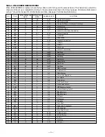
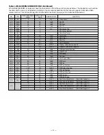
Table 1. ON-SCREEN SERVICE MENU (Continued)
When IC802 (EEPROM) is replaced, check the bus data to confirm they are the same as below. The shaded menu should be
checked and be set up or readjusted according to the procedures described in the following pages. Initial Setup Data
marked with an * should be changed from Initial Reference Data. (See page 3 for Initial Bus Data Setup.)
NO.
TITLE
INITIAL REFERENCE
INITIAL SETUP
RANGE OF DATA
FUNCTION
DATA
DATA
46
VL
4
4
0~7
Video Level
47
EWD
39
39
0~63
EW DC
48
EWA
30
30
0~63
EW Amp
49
EWT
34
34
0~63
EW Tilt
50
EWP
7
7
0~7
EW Corner Top
51
EWB
8
8
EW Corner Bottom
52
HSC
7
7
Horz Size Comp
53
SB
32
32
0~63
Sub Bright
54
SCO
7
7
0~31
Sub Color
55
STI
20
20
0~31
Sub Tint
56
SSH
12
12
0~31
Sub Sharpness
57
OPT
0
100*
0~255
Option (See Note 1 page 6.)
58
OP2
0
32*
0~255
Option 2 (See Note 2 page 6.)
59
HR
27
27
0~63
OSD Horizontal Position
60
ATT
7
7
0~63
Input Level
61
WDB
32
32
0~63
Wideband
62
SPC
32
32
0~63
Spectral
63
SBO
5
5
0~255
Sub Bright Offset
64
PCO
40
40
0~63
PIP Color
65
PTI
40
40
0~63
PIP Tint
66
PUV
24
24
0~63
PIP Top Position
67
PDV
147
147
0~255
PIP Bottom Position
68
PLH
10
10
0~63
PIP Left Position
69
PRH
101
101
0~255
PIP Right Position
70
PCN
42
42
0~63
PIP Y Level
71
PBS
15
15
0~63
PIP BGP Phase
72
DRV
64
64
0~127
Red Drive Adjustment
(See Note 3 page 6.)
64
64
0~127
Blue Drive Adjustment
(See Note 3 page 6.)
–
0
0
0~255
Red Bias Adjustment
(See Note 4 page 6.)
73
–
0
0
0~255
Green Bias Adjustment
(See Note 4 page 6.)
–
0
0
0~255
Blue Bias Adjustment
(See Note 4 page 6.)


