background image

— 4 —

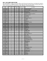
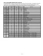
Table 1. ON-SCREEN SERVICE MENU

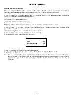
When IC802 (EEPROM) is replaced, check the bus data to confirm they are the same as below. The shaded menu should be
checked  and be set up or readjusted according to the procedures described in the following pages. Initial Setup Data marked
with an * should be changed from Initial Reference Data.  (See page 3 for Initial Bus Data Setup.)

NO.

TITLE

INITIAL REFERENCE

INITIAL SETUP

RANGE OF DATA

FUNCTION

DATA

DATA

01

HFR

29

29

0~63

Horizontal Frequency

02

AFC

0

0

0, 1

AFC Gain & Gate

03

HP

15

14*

0~31

Horizontal Phase  (Horizontal Centering)

04

VS

64

64

0~127

Vertical Size

05

VPO

5

5

0~63

Vertical Position

06

VSP

0

0

0, 1

Vertical Set Up (Sync Sensitivity)

07

VLN

18

13*

0~31

Vertical Linearity

08

CRS

0

0

0~3

Cross B/W

09

GRY

1

1

0, 1

Gray Mode

10

VSC

8

8

0~31

Vertical S Correction

11

HBR

3

3

0~7

H BLK R

12

HBL

4

4

0~7

H BLK L

13

CDM

0

0

0, 1

C D Mode

14

VC

7

7

0~7

Vertical Compression

15

RB

0

0

0~255

Red Bias

16

GB

0

0

0~255

Green Bias

17

BB

0

0

0~255

Blue Bias

18

RD

64

64

0~127

Red Drive

19

GD

8

8

0~15

Green Drive

20

BD

64

64

0~127

Blue Drive

21

SBI

48

48

0~127

Sub Bias

22

OSD

3

3

0~3

OSD Contrast

23

POS

0

0

0, 1

Pre/Over SW

24

FLS

1

1

0~7

Filter System

25

CKO

3

3

0~7

Color Killer Operation

26

GYA

0

0

0, 1

G-Y Angle

27

CRG

2

2

0~3

Coring Gain

28

PRE

1

3*

0~3

Pre Shoot Adjust

29

WP

1

1

0, 1

White Peak Limiter

30

FSW

0

0

0, 1

FBP Blanking Switch

31

VBL

0

0

0, 1

Vertical Blanking Switch

32

BSG

2

2

0~3

Black Str Gain

33

BSS

1

1

0~3

Black Str Start

34

DCR

1

1

0~3

DC Reset

35

YGM

1

1

0~3

Y Gamma

36

CBP

0

0

0, 1

C Bypass

37

AF

0

1*

0, 1

Auto Flesh

38

BAT

4

4

0~7

Bright ABL Threshold

39

MSD

0

0

0, 1

Mid Stop Def

40

ABL

0

0

0, 1

Auto Bright Limit

41

RYA

2

2

0~15

R-Y/B-Y Angle

42

RAD

15

15

0~63

RF AGC Delay

43

IAS

0

0

0, 1

IF AGC 

44

FMM

0

0

0, 1

FM Mute

45

FL

15

15

0~31

FM Level

Summary of Contents for DS25520

Page 1: ...ervice Adjustments 3 9 Purity and Convergence 10 11 Service Hints 12 Mechanical Disassemblies 13 Chassis Electrical Parts List 14 20 Cabinet Parts List 21 Component and Test Point Locations 22 24 Schematic Insert 25 32 Schematic Notes 25 Pin Layouts 25 Capacitor and Resistor Codes 25 Block Diagram 26 27 Voltage Charts 26 28 Waveforms 28 Schematic Diagram 29 32 SERVICE MANUAL Remote Control Color T...

Page 2: ...inet screw heads metal overlays control shafts etc Measure the AC voltage across the 1500 ohm resistor The AC voltage should not exceed 750 mV A reading exceeding 750 mV indicates that a dangerous potential exists The fault must be located and corrected Repeat the above test with the receiver power plug reversed NEVER RETURN A RECEIVER TO THE CUSTOMER WITHOUT TAKING THE NECESSARY CORRECTIVE ACTION...

Page 3: ...or detailed information INITIAL BUS DATA SETUP Note When IC802 EEPROM is replaced the Service Menu NO 03 HP H Phase NO 07 VLN V Lin NO 28 PRE Preshoot Adj NO 37 AF Auto Flesh NO 57 OPT SA Option and NO 58 OP2 SA Option 2 should be set up for proper TV operation before attempting the service adjustments 1 Disconnect the AC power cord AC 120V line 2 While pressing the MENU key reconnect the AC power...

Page 4: ...on 11 HBR 3 3 0 7 H BLK R 12 HBL 4 4 0 7 H BLK L 13 CDM 0 0 0 1 C D Mode 14 VC 7 7 0 7 Vertical Compression 15 RB 0 0 0 255 Red Bias 16 GB 0 0 0 255 Green Bias 17 BB 0 0 0 255 Blue Bias 18 RD 64 64 0 127 Red Drive 19 GD 8 8 0 15 Green Drive 20 BD 64 64 0 127 Blue Drive 21 SBI 48 48 0 127 Sub Bias 22 OSD 3 3 0 3 OSD Contrast 23 POS 0 0 0 1 Pre Over SW 24 FLS 1 1 0 7 Filter System 25 CKO 3 3 0 7 Col...

Page 5: ...54 SCO 7 7 0 31 Sub Color 55 STI 20 20 0 31 Sub Tint 56 SSH 12 12 0 31 Sub Sharpness 57 OPT 0 100 0 255 Option See Note 1 page 6 58 OP2 0 32 0 255 Option 2 See Note 2 page 6 59 HR 27 27 0 63 OSD Horizontal Position 60 ATT 7 7 0 63 Input Level 61 WDB 32 32 0 63 Wideband 62 SPC 32 32 0 63 Spectral 63 SBO 5 5 0 255 Sub Bright Offset 64 PCO 40 40 0 63 PIP Color 65 PTI 40 40 0 63 PIP Tint 66 PUV 24 24 ...

Page 6: ...ote control See Figure 2 The Drive Level adjustment data will be written in the Service Menu No 18 and 20 automatically 1 2 3 4 5 6 7 9 8 RB RB BB BB N A GB N A GB N A FOR RED BIAS ADJUSTMENT FOR BLUE BIAS ADJUSTMENT FOR GREEN BIAS ADJUSTMENT Figure 2 Figure 3 1 2 3 4 5 6 7 9 8 RD RD BD BD N A N A N A N A N A FOR RED DRIVE ADJUSTMENT FOR BLUE DRIVE ADJUSTMENT Note 4 Red Green Blue Bias Adjustments...

Page 7: ...o turn off the Service Menu display press the MENU key VERTICAL CENTERING ADJUSTMENT 1 Tune receiver to an active channel 2 Check that picture is in the center of TV screen If picture center is too low change resistor R513 from 1K ohm 1 2W to 470 ohm 1W If picture center is too high remove resistor R513 1K ohm 1 2W VCO ADJUSTMENT Note VCO must be adjusted after IC101 Signal Processor IC802 EEPROM ...

Page 8: ...power cord 6 While pressing the MENU key reconnect the AC power cord The Service Menu display will now appear 7 Select NO 53 SB Sub Brightness with or key 8 Adjust the data with or key for 820mVDC 9 Press the MENU key to turn off the Service Menu display 10 Check brightness level on every active channel readjust repeat steps 5 9 if necessary Note Do not set to excessive brightness level otherwise ...

Page 9: ...voltmeter RMS to TP317 and ground 4 While pressing the Menu key reconnect the AC power cord The Service Menu will now appear 5 Select NO 60 ATT Attenuation with the or key 6 Adjust the or key for a voltmeter reading of 400 20 mVrms at TP317 SEPARATION ADJUSTMENT 7 Turn off the receiver and disconnect the AC power cord AC 120V line 8 Connect oscilloscope CH1 to TP317 and CH2 to TP318 and ground 9 C...

Page 10: ...ust Service Menu NO 15 RB Red Bias NO 16 GB Green Bias and NO 17 BB Blue Bias data each to 0 8 Select Service Menu NO 73 no vertical sweep 9 Adjust the Screen Control counterclockwise until the horizontal scan line is no longer visible 10 Select Service Menu NO 16 GB Green Bias and increase the data to produce a green raster If retrace lines appear reduce screen control slightly 11 Pull yoke back ...

Page 11: ...D GREEN Adjust six pole tabs angle to superimpose red blue and green vertical line Adjust six pole tabs together to superimpose red blue and green horizontal line RED GREEN BLUE RED GREEN BLUE Line movement when adjusting top of yoke in and out Figure 7 Side of Yoke Movement OUTER AREA CONVERGENCE ADJUSTMENT The outer area convergence is performed by positioning of the yoke as follows 1 Move the t...

Page 12: ...ed on and any of these failures remains uncorrected the CPU will shut off the power within 3 seconds Check the following if the unit is turned off by the power failure detector 1 Disconnect the AC power cord 120V AC line for at least 10 seconds 2 Connect a DC Voltmeter to the following TEST POINTS 3 Press the Power key and check for the proper voltage supplies 4 If any of these voltages is low the...

Page 13: ...blies intact unless picture tube is being replaced Discharge the picture tube to the coating before handling the tube 1 Remove chassis referring to Chassis Removal instructions 2 Place cabinet s front face down on a soft surface 3 Remove the screw on each corner of the picture tube and GENTLY lift the picture tube out of the cabinet 4 Install a replacement picture tube in reverse order Properly in...

Page 14: ...cro Farad Material CERAMIC Ceramic MT PAPER Metalized Paper POLYESTER Polyester MT POLYEST Metalized Polyester POLYPRO Polypropylene MT POLYPRO Metalized Polypropylene COMPO FILM Composite Film MT COMPO Metalized Composite STYRENE Styrene TA SOLID Tantalum Solid AL SOLID Aluminum Solid ELECT Electrolytic NP ELECT Non Polarized Electrolytic OS SOLID Aluminum Solid with Organic Semiconductive Electr...

Page 15: ...50V 404 088 7102 CERAMIC 1000P M 250V C634 404 084 3207 ELECT 47U M 16V C683 404 084 3009 ELECT 220U M 16V C689 403 357 9601 CERAMIC 0 1U Z 50V C693 404 087 1200 ELECT 0 1U M 50V C701 403 235 5305 CERAMIC 1200P K 50V C711 403 224 5705 CERAMIC 1000P K 50V C721 403 224 5705 CERAMIC 1000P K 50V C742 403 077 2807 CERAMIC 1000P Z 2K C801 403 224 6108 CERAMIC 0 01U K 50V C806 404 084 2408 ELECT 470U M 6...

Page 16: ...06 0100 DIODE ERA91 02 D624 407 106 2806 DIODE RU3YX D625 407 129 7000 DIODE RU4AM LF L1 407 211 5808 DIODE FE201 6L43 D627 407 013 4306 DIODE 1S2076A 407 013 7109 DIODE 1S2473 408 008 2406 DIODE 1N4148 D629 407 054 7007 ZENER DIODE RD16EB1 16V 407 099 7208 ZENER DIODE MTZJ16A 16V D680 407 013 4306 DIODE 1S2076A 407 013 7109 DIODE 1S2473 408 008 2406 DIODE 1N4148 D683 407 013 4306 DIODE 1S2076A 40...

Page 17: ...5 GR SAN Q401 405 013 6207 TR 2SC2271 D CTV 405 013 6306 TR 2SC2271 E CTV 405 029 7106 TR 2SC2271 D 405 029 7205 TR 2SC2271 E Q402 405 153 0202 TR 2SD2578 YB Q486 405 023 5009 TR 2SD400 E MP 405 023 5306 TR 2SD400 F MP Q490 405 023 5009 TR 2SD400 E MP 405 023 5306 TR 2SD400 F MP Q601 405 166 7601 TR 2SK2872 Q611 405 013 6801 TR 2SC2274 E 405 013 7006 TR 2SC2274 F Q612 405 006 6504 TR 2SA984 E 405 ...

Page 18: ...A 1 10W R212 401 256 7100 MT GLAZE 680K JA 1 10W R251 401 162 3005 MT GLAZE 22K JA 1 10W R252 401 025 8208 CARBON 22K JA 1 6W R272 401 256 7308 MT GLAZE 6 8K JA 1 10W R273 401 150 5905 MT GLAZE 10K JA 1 10W R274 401 162 4101 MT GLAZE 5 6K JA 1 10W R276 401 024 9701 CARBON 12K JA 1 6W R281 401 150 5905 MT GLAZE 10K JA 1 10W R284 401 026 9303 CARBON 47 JA 1 6W R287 401 255 6500 MT GLAZE 100 JA 1 10W...

Page 19: ...DE MT 12K JA 2W R721 401 025 3807 CARBON 180 JA 1 6W R723 401 256 0309 MT GLAZE 820 JA 1 10W R724 401 027 8107 CARBON 82 JA 1 6W R726 401 009 1508 CARBON 2 7K JA 1 2W R727 401 065 4604 OXIDE MT 12K JA 2W R803 401 024 6700 CARBON 100 JA 1 6W R804 401 024 6700 CARBON 100 JA 1 6W R806 401 162 3708 MT GLAZE 4 7K JA 1 10W R807 401 150 5905 MT GLAZE 10K JA 1 10W R808 401 150 5905 MT GLAZE 10K JA 1 10W R...

Page 20: ...027 7382 SWITCH PUSH CH 645 052 2284 SWITCH PUSH CH SW1906 645 006 9673 SWITCH PUSH MENU 645 027 7382 SWITCH PUSH MENU 645 052 2284 SWITCH PUSH MENU TRANSFORMERS T151 645 049 3775 TRANS OSC 45 75MHZ T401 652 000 1442 TRANS DRIVE T402 645 045 8521 TRANS FLYBACK T601 645 051 2384 TRANS POWER PULSE 645 051 4951 TRANS POWER PULSE CRYSTAL FILTERS X141 421 008 9008 SAW F TSF5235P X161 610 015 3059 TRAP ...

Page 21: ...EW 4X14 7 USED OR 411 078 1101 SCREW 4X14 7 USED 7 412 018 8402 SCREW 3X10 1 USED 8 610 296 9610 BUTTON UNIT 9 610 285 1199 CAP RC 10 610 293 2560 SANYO BADGE LARGE SILVER 610 297 8919 OWNER S MANUAL 645 053 8698 RC TRANSMITTER OR 645 053 8711 RC TRANSMITTER 645 048 1352 RC BATTERY COVER OR 610 290 1283 RC BATTERT COVER CABINET PARTS LIST KEY NO PARTS NO DESCRIPTION ACCESSORY PARTS LIST KEY NO PAR...

Page 22: ...51 C1001 C1059 D1001 D1052 D1051 J1051 J1052 R1059 C1002 D1002 C011 C010 C3417 C3411 C3441 C3408 C3413 C3414 C3401 C3412 C3432 C3424 C3404 C3416 C3418 KSP C3442 C3447 C3448 C3437 C3435 C3427 J3403 R421 D801 D806 Q1071 K1001 K1003 J104 J402 J013 C002 C001 J3401 J3402 J3404 C015 J017 R486 R489A R487 D486 J1011 L1001 J1004 C1081 R833 J144 D472 J1006 J449 J446 J209 C274 R495A C151 L136 X141 X141A L146...

Page 23: ...84 J447 Q490 R499 D490 R488 R402 R284 C497 J453 J841 R252 R441 R443 R444 J492 J142 J811 R1910 R1909 R823 R829 J808 J448 J481 J812 J809 J482 J134 J201 J608 R511A R489 A1901 J3471 L3401 D836 R832 R495 R472 C489 Q486 J502 L812 R846 R847 J842 J843 R849 R848 L863 IC802 C806 C802 C811 C822 L821 L851 C856 C851 X801 C853 C829 D834 D843 L811 J803 L801 R883 R884 J851 J852 J802 J814 J441 J443 J445 J1013 J211...

Page 24: ...Q711A Q711 Q721 R707 R704 R721 R711 C702 R717 R727 SCREEN R701 R724 K7S R716 K7B GND R707A R717A R727A PICTURETUBE SOCKET BOARD April 2002 2000 SMC Printed in U S A For parts or service contact 21605 Plummer Street Chatsworth CA 91311 U S A 300 Applewood Crescent Concord Ontario L4K 5C7 CANADA SANYO Fisher Service Corporation COMPONENT ANDTESTPOINT LOCATIONS Cont ...

Page 25: ...E CB E C B E C B E CB E C B E C B E C B 3 2 1 3 2 1 GND 2 IN 1 OUT 3 1 1 TOP VIEW 1 CHIP TRANSISTORS B C E TOP VIEW B BASE C COLLECTOR E EMITTER CHIP RESISTORS TOP VIEW 123 12 x 10 12K ohm 3 NOTES ON SCHEMATIC DIAGRAMS 1 All resistance values in ohms K 1 000 M 1 000 000 2 Unless otherwise noted on schematic all capacitor values less than 1 are expressed in µF Micro Farad and the values more than 1...

Page 26: ...C EM4 7 LBWA 1 10GJ 100KC 1 10GJ 560C EM4 7 LBWA 16EM 220 LBWA 1 10GJ100C 1 10GJ100C 1 10GJ100C 1 10 GJ1KC KK 0 01 LZB UPC78L05J TA78L05S 4A125V M MD MDK T EM2 2 LBWA 1 2DJ 1 2 47 6 3EM 220 1 10GF 3 3KC 18K LA78041 FK0 15D FJ0 15D 2SJ 120 25EM 2200 LBWA 35EM 220 CJ56CL FK5600 BF D 3 9K EK 2 2AE 560 10K 6 8K 18K X X J 16EM 10 LBWA 1 10 GJ18KC 18K 1 2DJ1 100 100 16EM 22 LBWA 1 10 GJ 10KC 1 10GJ 2 2K...

Reviews: