background image

Page 15


Document No. 

Document Name 

SANYO Electric Co., Ltd. 

Reliability  

 (3/3) 

The following table shows the reliability standards for the main parts (units) which are used in 
this product. 

Test items 

Test conditions 

Criteria 

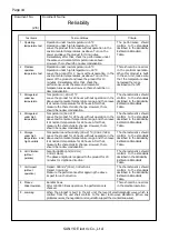
10.  Laser diode life 


Check the recorded power after 1000 hours of 

operation at 60 

°

C. 

(except for breakage caused by static electricity) 

The error rate should be 
1 % or less. 

11.  Spindle motor life 

Measure the current in the motor after 1000 hours 

operation. 

The initial value should be 
+35 % or less. 

12.  Feeder motor life 


After the pick-up slide operation as described in item 

8, measure the consumption current in the motor. 

The values should be 
conform to the pull-out 
torque 1500pps 9.8×10-

4


N-m (10grf-cm) or more. 


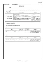
3. Reliability Standards 

The reliability standards are as follows. 

1).CD 

 
2).DVD 


Items Before 

Test 

Change in 

Values after Test 

Remarks 

1/3 stroke mean access 

time 

×

40 CAV   

speed 

0.27 s or less 

0.35 s or less 

Mean value measured after 
reciprocating operation for (0 
to 20) min. (one way value) 

Items Before 

Test 

Change in 

Values after Test 

Remarks 

1/3 stroke mean access 

time 

×

12 CAV   

speed 

0.27 s or less 

0.35 s or less 

Mean value measured after 
reciprocating operation for (0 
to 20) min. (one way value) 

Summary of Contents for CRD-BPDV2

Page 1: ......

Page 2: ......

Page 3: ...Page 2 Document No Document Name SANYO Electric Co Ltd Revision History 1 1 1 Revision History Revision No Manager Change Description Check Approval First Edition Newly issued ...

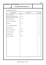
Page 4: ...tion 1 3 3 3 4 Dimensions External View and Names and Functions of Each Part 1 2 2 2 7 Terminal Description 1 3 3 3 9 Environmental Conditions 1 1 12 Reliability 1 3 3 3 13 Lot No Reliability Description 1 1 16 Safety Standards 1 1 17 Electrical Characteristics 1 3 3 3 18 Function Description 1 3 3 3 21 Handling Manual 1 1 24 Notes for Handling 1 5 5 5 25 ...

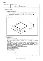
Page 5: ...ok Part 2 3 DVD R RW for general specifications Equipped with the newly developed automatic strategy LSI with the data reliability enhanced DVD R RW drive with MAX 12 speed reading CAV 4 speed writing CLV 2 speed rewriting CLV DVD R RW drive with MAX 12 speed reading CAV 4 speed writing CLV 2 4speed rewriting CLV CD R drive with MAX 40 speed reading 24 speed writing ZCLV and 12 rewriting CLV ATAPI...

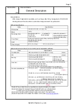
Page 6: ...ME 2000 NT4 0 XP Note 2 Memory MS Windows 98SE ME NT 128 MB or more MS Windows2000 WindowsXP 128 MB required 256 MB recommended Hard disc Empty Storage Capacity 5GB or more 20GB or more recommended Average seek time 20 ms or less Transmission rate 2 MB s or more Do not use the HDD which calibrate thermal during operation CD R 4 40 MITSUI CHEMICAL HITACHI MAXELL RITEK ACER CMC T B D CD RW 4 10 12 M...

Page 7: ...W DVD R RW disc Read of CD ROM DVD ROM disc 4 Dimensions Refer to the item Dimensions and Dimensional Drawing 5 Notes for handling Refer to the Manual and Notes for Handling 6 Others a The specifications of this product are the same as in the delivery specifications If any fault or malfunction of the product occurs when it is used under any conditions except for our guaranteed conditions our compa...

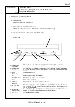
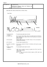
Page 8: ...rminal is adjusted using this volume dial When the volume dial is turned right the volume becomes louder 3 BUSY indicator Command executing ON Reading disc and accessing condition ON AND OFF TOC reading condition EJECT condition OFF Pause or Stop condition 4 WRITE indicator This is ON when the data is written onto the disc 5 EJECT key The disc is ejected using this key This key is available even w...

Page 9: ...ive inside the personal computer Default is Master 3 IDE Connector Using a 40 pin connector the ATAPI terminal of the host computer is connected to this connector 4 DC Connector This is the power supply terminal 5 FACTORY USE ONLY Pins These pins are used only for the test in the factory Don t cover the jumper block on them 6 DIGITAL AUDIO Connector The audio digital signal output connector 7 UDMA...

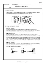
Page 10: ...mper Terminals To set to Master mode cover the jumper block on the 2 pins of the MA jumper terminals If the IDE controller of the personal computer supports up to four devices set the CD R drive to either a Primary Slave a Secondary Master or a Secondary Slave mode Primary or Secondary is set up by the IDE controller while Master or Slave mode is set up by covering the jumper block on the rear of ...

Page 11: ...E cable of the color coding normally red on one edge to pin No 1 PIN NO SIGNAL NAME PIN NO SIGNAL NAME 2 Ground 1 RESET 4 DD8 3 DD7 6 DD9 5 DD6 8 DD10 7 DD5 10 DD11 9 DD4 12 DD12 11 DD3 14 DD13 13 DD2 16 DD14 15 DD1 18 DD15 17 DD0 20 keypin 19 Ground 22 Ground 21 DMARQ 24 Ground 23 DIOW STOP 26 Ground 25 DIOR HDMARDY HSTROBE 28 CSEL 27 IORDY DDMARDY DSTROBE 30 Ground 29 DMACK 32 reserved 31 INTRQ ...

Page 12: ...Page 11 Document No Document Name SANYO Electric Co Ltd Terminal Description 3 3 4 DC Connector Terminals DC INPUT The DC power supply cable is connected through these terminals 5V 12V GND ...

Page 13: ...ondensing Storage 90 40 C 48 h Mean Time Between Failure MTBF 30000 POH DUTY 20 read operation Note 1 Life Tray loading 20000 cycles Traverse mechanism 1000000 seek Vibration Operation Read 0 98 m s2 0 1 G 10 to 500 Hz Random Vibration Without operation transportation 800 cpm 13 3 Hz 3 mm 1 06 G Up Down 20 min Impact Drop Impact 490 m s2 50 G 3 directions 6 ms Note 1 POH Power On Hour live current...

Page 14: ...W RICOH MITSUBISHI CHEMICAL DVD R R RICOH MITSUBISHI CHEMICAL DVD RW RW RICOH MITSUBISHI CHEMICAL However when no doubt occurs regarding the judgment TCD 784 made by ALMEDIO Inc may be used 4 Power Supply Voltage Power supply DC 5 1 5 V Power supply DC 12 1 10 V 2 Reliability The results should conform to the criteria of each item after the test has been performed under the following conditions Th...

Page 15: ...andards Table 4 Storage test under high temperature Temperature 60 2 C Leave the product for 24 hours without operation in the above environmental temperature range and then leave it at normal temperature for 24 hours After that measure the characteristic change However there should be no dew condensation The characteristics should conform to the standards described in the Reliability Estimation S...

Page 16: ...ess 12 Feeder motor life After the pick up slide operation as described in item 8 measure the consumption current in the motor The values should be conform to the pull out torque 1500pps 9 8 10 4 N m 10grf cm or more 3 Reliability Standards The reliability standards are as follows 1 CD 2 DVD Items Before Test Change in Values after Test Remarks 1 3 stroke mean access time 40 CAV speed 0 27 s or le...

Page 17: ...Electronics 6 Sanyo Media Tech 3 SSHQ 8 B Year of manufactured 1996 6 1997 7 1998 8 1999 9 2000 0 2001 1 2002 2 2003 3 2004 4 2005 5 C Month of manufactured Form Jan to Sep 1 9 Form Oct to Dec X Z Jan 1 Feb 2 Mar 3 Apr 4 May 5 Jun 6 Jul 7 Aug 8 Sep 9 Oct X Nov Y Dec Z D Manufacturing Serial No Start from 00001 5 digits When the number reach to 99999 the next is 00000 then 00001 again ...

Page 18: ...Page 17 Document No Document Name SANYO Electric Co Ltd Safety Standards 1 1 Safety Standards 1 UL UL1950 FDA1040 2 CUL UL1950 3 Label ...

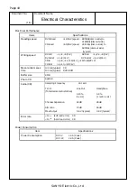
Page 19: ...V DVD RW 1 2 CLV DVD RW 1 2 4 CLV CD R 4 8 12 16 CLV 16 24 ZCLV CD RW 4 10 12 CLV Mean random seek time 130 ms typical CD 130 ms typical DVD ROM Buffer size 8 MB Photo CD Applied Sampling Frequency 44 1 kHz Line Out Headphone T H D Total Harmonic Distortion 0 15 1 kHz 0 4 1 mW 1 kHz Channel Separation 60 dB 28 dB Audio CD S N ratio 70 dB 65 dB Max Output 0 6 V typical 0 8 V typical Error rate 10 9...

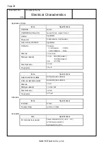
Page 20: ...us Astigmatism Tracking DPP DPD Wave length 784 660 nm standard Traverse mechanism Stepping motor Spindle motor DC brushless motor Loading mechanism Automatic loading system Media name Capacity Reading Writing DVD ROM single 4 7GB DVD ROM dual 8 7GB DVD RAM V1 0 2 6GB DVD RAM V2 0 4 7GB DVD R V2 0 for General 4 7GB DVD RW V1 1 4 7GB DVD R V1 0 4 7GB DVD RW 4 7GB ...

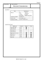
Page 21: ...ond Session Data Disc dia 12 cm 8 cm Storage capacity 12 cm 656 MB mode 1 748 MB mode 2 8 cm 180 MB Disc thickness 1 2 mm Track pitch 1 6 µm Items Specifications DVD R RW DVD ROM DVD ROM DVD VIDEO DVD R RW DVD ROM DVD ROM DVD VIDEO Disc dia 12 cm Storage capacity 12 cm 4 7GB Disc thickness 1 2 mm Track pitch 0 74 µm Interface Items Specifications Interface ATAPI Transfer Rate U DMA 33 MB s Connect...

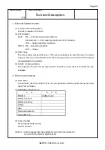
Page 22: ...ey is not available under the recording condition or when the PRV command is transmitted from the HOST 4 8 cm 12 cm disc applicable The read of 8 cm and 12 cm pit discs and the write of 12 cm pit discs of the CD R disc are available 2 Data read processing 1 Read speed The standard CD Max 24 DVD Max 12 are applicable Arbitrary speed can be set using the ATAPI command 2 Read data mode Note 1 1 C D D...

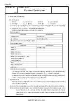
Page 23: ...C Media catalogue No CD TEXT 4 Optimum write function The strategy and write laser power are set automatically according to the characteristics of the disc This is performed when the disc is replaced or the CLV speed is changed In addition the write condition is checked during writing the data and the running OPC function which sets the optimum laser power is performed 5 BURN Proof Seamless Linkin...

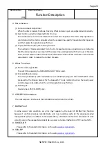
Page 24: ...umber of seeks 5 Other Functions 1 Multi volume applicable To switch the sessions the SESSION SELECTOR is used 2 Disc identification codes The discs produced by each manufacturer are identified using the disc identification codes prepared by the Orange Society for the Research This is referred to when the laser power and strategy are decided when the writing operation is performed 3 Device type De...

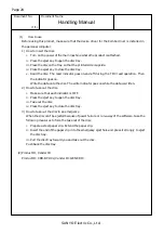
Page 25: ...oes on Write the data onto the disc The write indicator goes on while the data is written 2 How to take out the disc i Make sure that each indicator is OFF ii Press the eject key to open the disc tray iii Take out the disc iv Press the eject key to close the disc tray 3 How to take out the disc in an emergency When the disc can t be ejected because of power failure or run away of the software take...

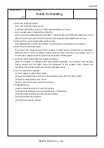
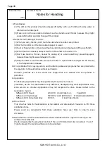
Page 26: ...rom your hands or static electricity Also don t touch the connector part on the personal computer when this product is connected or disconnected 5 Don t connect and disconnect this product excessively When this product is connected and disconnected repeatedly the connector part becomes heavily loaded and this might cause the breakdown of this product Don t connect and disconnect this product exces...

Page 27: ...ted from copying selling and transfering datas and programs that are protected by the copyright to the authorities without permission However personal use of the sound and images that are recorded with this product is permitted 11 Application The following applications may be supported by this product in future Therefore we are not responsible for any defects or damages using other applications Al...

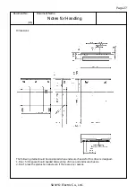
Page 28: ...es for Handling 3 5 Dimensions The following items should be considered when enclosure chassis for this drive is designed 1 Over 5 mm space should needed between top of drive and enclosure chassis 2 Don t press the production label even if there are any reasons ...

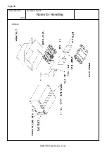
Page 29: ...Page 28 Document No Document Name SANYO Electric Co Ltd Notes for Handling 4 5 Package ...

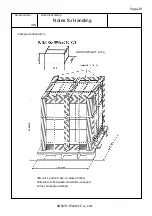
Page 30: ...nt No Document Name SANYO Electric Co Ltd Notes for Handling 5 5 Package Configuration GROSS WEIGHT 12 kg 300 unit 1 pallet 6 box 5 stack 30 box Pallets are to be banded and stretch wrapped Corner strips are attached ...

Reviews: