background image

16

4.  Air Purging

Air and moisture remaining in the refrigerant system have

undesirable effects as indicated below. Therefore, they

must be purged completely.

G

pressure in the system rises

G

operating current rises

G

cooling efficiency drops

G

moisture in the air may freeze and block capillary tubing

G

water may lead to corrosion of parts in the refrigerant

system

I

Air Purging with a Vacuum Pump 
(for Test Run)

G

In order to protect the earth’s environment, be sure to use

a vacuum pump to perform the air purge.

(Never perform an air purge by using the refrigerant gas

cylinder or other external gas, or by using the gas inside

the outdoor unit.)

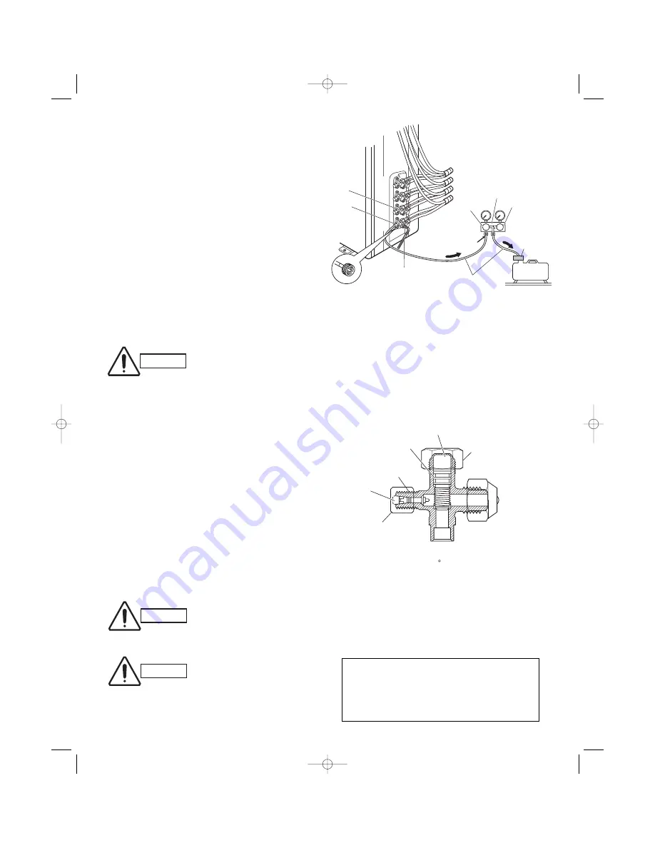
Perform the air purge for tubes A, B, C, and D. Use the

same procedures for all tubes.

(1) Check that each tube (both narrow and wide tubes)

between the indoor and outdoor units have been

properly connected and all wiring for the test run has

been completed. Note that both narrow and wide tube

service valves on the outdoor unit are kept closed at

this stage.

(2) Using an adjustable wrench or box wrench, remove

the valve caps from the service valve on both narrow

and wide tubes.

(3) Connect a vacuum pump and a manifold valve (with

pressure gauges) to the service port on the wide tube

service valve. (Fig. 20).

Fig. 20

Fig. 21

CAUTION

Be sure to use a manifold valve for
air purging. If it is not available,
use a stop valve for this purpose.
The “Hi” knob of the manifold
valve must always be kept closed.

CAUTION

CAUTION

Before using the vacuum pump
adapter, read the vacuum pump
adapter manual, and use the
adapter correctly.

In order to prevent charging errors with
A/C that uses R410A, the screw diameter
at the service valve charging port has
been changed. When recharging or per-
forming other servicing, use the special
charging hose and manifold gauge.

G

When using a hex wrench to open the spindle, an

extremely small amount of refrigerant may leak. 

This does not indicate a problem.

G

Use a hex wrench of a type to which force can be

easily applied. 

Service 
valve on 
wide tube 
side

Service 
valve on 
narrow 

A

B

C

D

Vacuum 
pump

Vacuum pump 
adapter 
(for preventing 
reverse flow)
(special for 
R410A)

High-pressure valve

Manifold gauge 
(special for R410A)

Low-pressure 
valve

Leave the 
valve open.

Open

Charging hose
(special for R410A)

Hex wrench 

With push-pin

Hi

Lo

Cap tightening torque:
170 – 215 lbs·in
(200 – 250 kgf·cm)
(Tighten by hand, then 
use a wrench to turn.) 

Stopper

Spindle

Screw diameter: 1/2
UNF 20 threads

Valve core

Cap nut tightening torque:
60 – 95 lbs·in
(70 – 110 kgf·cm)
(Tighten by hand, then use a 
wrench to turn approximately 30 .)

<Structure of service valve on wide tube side>

05-352 KMHS0772_outdoor  3/17/06  2:56 PM  Page 16

Summary of Contents for CMH1972

Page 1: ...n 5 WIRING INSTRUCTIONS 19 5 1 General Precautions on Wiring 5 2 Recommended Wire Length and Diameter 5 3 Wiring System Diagram 5 4 How to Connect Wiring to the Terminal 5 5 Wiring Instructions for the Outdoor Unit 6 TEST RUN 23 7 CONNECTING A HOME AUTOMATION DEVICE 24 8 INSTALLATION CHECK SHEET 24 INSTALLATION INSTRUCTIONS Model Combinations Combine indoor and outdoor units only as listed below I...

Page 2: ... the indoor and out door units Get a partner to help and bend your knees when lifting to reduce strain on your back Sharp edges or thin alu minum fins on the air conditioner can cut your fingers When Installing In a Ceiling or Wall Make sure the ceiling wall is strong enough to hold the unit s weight It may be necessary to construct a strong wood or metal frame to provide added support In a Room P...

Page 3: ...y from a local source you will need 1 Deoxidized annealed copper tube for refrigerant tub ing as detailed in Table 2 Cut each tube to the appropriate lengths 1 to 1 4 30 cm to 40 cm to dampen vibration between units Table 2 2 Foamed polyethylene insulation for the specified copper tubes as required to precise length of tubing Wall thickness of the insulation should be not less than 5 16 8 mm 3 Use...

Page 4: ...weight of the unit G select a location where tubing and drain hose have the shortest run to the outside Fig 1 G allow room for operation and maintenance as well as unrestricted air flow around the unit Fig 2 G install the unit within the maximum elevation difference H1 H2 H3 H4 above or below the outdoor unit and within a total tubing length L1 L2 L3 L1 L2 L3 L4 from the outdoor unit as detailed i...

Page 5: ... ft Max charge additional refrigerant R410A by 0 22 oz ft No additional charge of compressor oil is necessary Max Max Allowable Total Limit of Limit of Elevation Required Amount Allowable Tubing Length Total Tubing Length Difference of Additional Model Tubing Length at shipment L1 L2 L3 or H1 H2 H3 H4 Refrigerant per unit L1 L2 L3 or L1 L2 L3 L4 ft oz ft ft L1 L2 L3 L4 ft ft CMH1972 82 150 L1 L2 L...

Page 6: ... KMHS0972 KMHS1272 KMHS0772 KMHS0972 KMHS1272 D Outdoor unit Indoor unit KMHS0772 KMHS0972 KMHS1272 KMHS0772 KMHS0972 KMHS1272 1 2 12 70mm 3 8 9 52mm 3 8 9 52mm 3 8 9 52mm 3 8 9 52mm 3 8 9 52mm 3 8 9 52mm 3 8 9 52mm 1 4 6 35mm 1 4 6 35mm 1 4 6 35mm 1 4 6 35mm 2 Connecting indoor unit for CMH2472 A Fig 4a 3 8 9 52mm 3 8 9 52mm 1 4 6 35mm 1 4 6 35mm 1 4 6 35mm 3 8 9 52mm 3 8 9 52mm 3 8 9 52mm 3 8 9 ...

Page 7: ...72 KMHS0972 KMHS1272 KMHS2472 Union 1 2 12 70mm Flare 3 8 9 52mm 3 8 9 52mm 1 2 12 70mm Locally purchased 1 2 12 70mm 1 2 12 70mm 5 8 15 88mm 3 8 9 52mm 3 8 9 52mm 3 8 9 52mm 3 8 9 52mm 3 8 9 52mm 1 4 6 35mm 1 4 6 35mm 1 4 6 35mm 1 4 6 35mm C Fig 4e Union 5 8 15 88mm Flare 1 2 12 70mm 1 2 12 70mm 5 8 15 88mm Locally purchased C B A KMHS0772 KMHS0972 KMHS1272 KMHS0772 KMHS0972 KMHS1272 D Outdoor un...

Page 8: ...9 52mm Flare 1 2 12 70mm 1 2 12 70mm 3 8 9 52mm Supplied Reducer C B A KMHS0772 KMHS0972 KMHS1272 KMHS0772 KMHS0972 KMHS1272 D Outdoor unit Indoor unit KMHS0772 KMHS0972 KMHS1272 KMHS1872 1 2 12 70mm 1 2 12 70mm 1 2 12 70mm 3 8 9 52mm 3 8 9 52mm 3 8 9 52mm 3 8 9 52mm 3 8 9 52mm 1 4 6 35mm 1 4 6 35mm 1 4 6 35mm 1 4 6 35mm C Fig 4i C B A KMHS1872 KMHS0772 KMHS0972 KMHS1272 D Outdoor unit Indoor unit...

Page 9: ...m 1 2 12 70mm 5 8 15 88mm 3 8 9 52mm 3 8 9 52mm 3 8 9 52mm 3 8 9 52mm 3 8 9 52mm 1 4 6 35mm 1 4 6 35mm 1 4 6 35mm 1 4 6 35mm E Fig 4k Union 5 8 15 88mm Flare 1 2 12 70mm 1 2 12 70mm 5 8 15 88mm Locally purchased C B A KMHS1872 KMHS0772 KMHS0972 KMHS1272 D Outdoor unit Indoor unit KMHS0772 KMHS0972 KMHS1272 KMHS2472 1 2 12 70mm 1 2 12 70mm 5 8 15 88mm 3 8 9 52mm 3 8 9 52mm 1 2 12 70mm 3 8 9 52mm 3 ...

Page 10: ...ll cushion rubber under unit s feet to reduce vibration and noise Fig 5e G use lug bolts or equal to bolt down unit reducing vibration and noise G Install in a location where no antenna of a television or radio exists within 10 3 m Outdoor unit Hot air Heat source Exhaust fan NO Fig 5a Fig 5b Fig 5d Air intake Min 8 20 cm Air discharge Min 4 10 cm Min 1ʼ8 50 cm Valve side Min 10 25 cm Min 7 2 m Mi...

Page 11: ...5 16 2 3 4 Service valve on narrow tube side Outer diameter 1 4 6 35 Service valve on wide tube side Outer diameter 3 8 9 52 Service valve on wide tube side Outer diameter 1 2 12 70 A 23 32 Fig 6c 23 15 16 15 32 12 19 32 13 19 32 14 17 32 5 11 32 35 7 16 900 23 32 35 1 32 890 2 29 32 2 1 16 1 13 16 2 13 32 4 1 2 2 1 32 4 7 16 5 29 32 2 15 16 2 27 32 2 3 4 2 3 4 A Service valve on narrow tube side ...

Page 12: ...ed in order to maintain performance Install in a location where the dimensions indicated by are ensured and where 2 or more faces of the unit are unobstructed In principle the top direction should be unobstructed Indoor unit C Indoor unit B Indoor unit A Indoor unit D Service space Power breaker Ground wire not provided Ensure 6 15cm of space if a drain hose is to be used Base not provided concret...

Page 13: ... wire ends to contact rainwater or be subject to dew condensation Deburring Before After Fig 8 3 2 Use of the Flaring Method Many of the conventional split system air conditioners employ the flaring method to connect refrigerant tubes which run between indoor and outdoor units In this method the copper tubes are flared at each end and connected with flare nuts 3 3 Flaring Procedure with a Flare To...

Page 14: ...ch other then screw in the flare nut lightly at first to obtain a smooth match Fig 13 3 5 Tubing Connections a Temporary connection Screw in 3 5 rotations by hand Fig 14 b To fasten the flare nuts apply specified torque as Table 4 NOTE NOTE Reamer Copper tubing Fig 9 Flare tool Flare nut Copper tubing Fig 11 Fig 10 Apply refrigerant lubricant here and here Fig 12 Flare nut Union Fig 13 0 to 0 0196...

Page 15: ...wind the armoring tape too tightly since this will decrease the heat insulation effect Also be sure the con densation drain hose splits away from the bundle and drips clear of the unit and the tubing 3 8 Finishing the Installation After finishing insulating and taping over the tubing use sealing putty to seal off the hole in the wall to prevent rain and draft from entering Fig 19 NOTE IMPORTANT In...

Page 16: ...service valve Fig 20 Fig 20 Fig 21 CAUTION Be sure to use a manifold valve for air purging If it is not available use a stop valve for this purpose The Hi knob of the manifold valve must always be kept closed CAUTION CAUTION Before using the vacuum pump adapter read the vacuum pump adapter manual and use the adapter correctly In order to prevent charging errors with A C that uses R410A the screw d...

Page 17: ...in 6 With a hex wrench turn the valve stem on the nar row tube service valve counter clockwise by 90 degrees 1 4 turn for 10 seconds and then turn the stem clockwise to close it again 7 With a standard screwdriver turn the wide tube service valve stem counterclockwise to fully open the valve 8 Turn the narrow tube service valve stem counter clockwise to fully open the valve 9 Loosen the vacuum hos...

Page 18: ...ifold gauge and the inter unit tubes and attach the caps and flare nuts At this point pump down is com pleted If the caps and flare nuts are not reattached there is the danger of gas leakage Refer to Fig 24 If pump down is not possible If the A C cannot be operated because of a malfunction or other cause use a refrigerant recovery device to recover the refrigerant In order to protect the earth s e...

Page 19: ...can be very dangerous The manufacturer will accept no responsibility for any damage or misoperation that occurs as a result of such unauthorized changes 5 2 Recommended Wire Length and Diameter Regulations on wiring diameter differ from locality to locality For field wiring requirements please refer to your local elec trical codes Carefully observe these regulations when car rying out the installa...

Page 20: ...Place a dedicated ground more than 7 2 m away from other grounds and do not have it shared with other electric appliances WARNING Fig 25a Fig 25b 4 indoor units with CMH2472 CMH3172 1 2 3 Terminal INDOOR UNIT 1 2 3 INDOOR UNIT 1 2 3 1 UNIT B 2 3 4 UNIT C 5 6 7 8 9 1 2 Terminal Terminal L1 L2 INDOOR UNIT UNIT A A B C Terminal 2P Terminal 9P OUTDOOR UNIT Disconnect switch 230 208V 230 208V 230 208V ...

Page 21: ...erly place it on the termi nal plate and fix it securely with the removed termi nal screw using a screwdriver I For stranded wiring 1 Cut the wire end with a cutting pliers then strip the insulation to expose the stranded wiring about 3 8 10 mm and tightly twist the wire ends Figs 28 and 29 2 Using a screwdriver remove the terminal screw s on the terminal plate 3 Using a ring connector fastener or...

Page 22: ...e valve A top of the outdoor unit refrigerant tubing that is connected to service valve B top of the outdoor unit B is the indoor unit with refrigerant tubing that is connected to service valve C top of the outdoor unit C is the indoor unit with refrigerant tubing that is connected to service valve D top of the outdoor unit D is the indoor unit with 1 2 1 2 3 4 5 6 7 8 9 10 11 12 Power supply cond...

Page 23: ...tallation manual G Perform the test run separately for each connected indoor unit If 2 units are operated simultaneously it is not possible to correctly check for errors in tubing and wiring G If the room temperature is 59 F 15 C or below it may not be possible to check for tubing errors with cooling operation If this occurs perform heating operation for each unit individually and check that warm ...

Page 24: ...ened to the terminal board Inter unit cables are securely fixed The power cord and inter unit cables are not connected anywhere along their paths The ground wire is securely connected An air purge of the refrigerant circuit has been conducted A leak test of the tubing connections has been performed Thermal insulation has been applied to the tubing connections Drain connections are secure and water...

Reviews: