background image

INSTALLATION (For under dash)

NO TES:

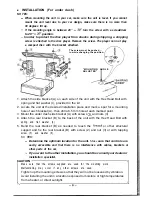
When mounting the unit in your car, make sure the unit is level. If you cannot

mount the unit level due to your car design, make sure there is no more than
30 degrees tilt up.

If the mounting angle is between 20”   

 turn the screw with a screwdriver

to 20”   

 position.

 In order to protect the disc player from shocks during shipping, a shipping

screw is attached to the disc player. Remove the screw. The player can not play
a compact disc with the bracket attached.

The screw must be pushed 

in while changing the position.

“ M O U N T I N G   A N G L E
A D J U S T E R ”

1. Attach the side bracket (A) on each side of the unit with the Hex Head Bolt with

spring and flat washer (I), provided in the kit.

2. Locate the unit at the desired installation place and mark a spot for a mounting

hole of each bracket (A), then drill a 6.5 mm hole at each marked point.

3. Mount the under dash side bracket (A) with screws 

 and nuts (3).

4. Attach the rear bracket (B) to the back of the unit with the Hex Head Bolt with

spring and flat washer (4).

5. Bend the rear bracket (B) as needed to reach the 

 or other structural

support and fix the rear bracket (B) with screw (2) and nut (3) or with tapping
screw (5) and washer (6).

NO 

TES:

Determine the optimum location for the unit. 

Make 

sure that controls are

easily accessible and that there is no interference with cables, brackets or
other parts of the car,
If you want to the other installation, you should be consult your dealer or
installation specialist.

CAUTION

Make sure that the screws supplied are used for the mounting work.
Malfunctioning may occur if any other screws are used.
Tighten up the mounting screws so that they will not be loosened by vibration.
Avoid installing the unit in a location exposed to moisture or high temperatures

from a heater, or direct sunlight.

Summary of Contents for CDF-201A

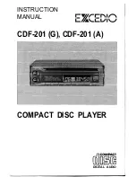
Page 1: ...INSTRUCTION MANUAL CDF 201 G CDF 201 A COMPACT DISC PLAYER flrE DIGITAL AUDIO ...

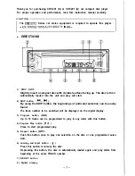
Page 2: ...utton F w By using the SKIP button the beginnings of particular selection can be easily found The track number to be searched will be displayed on the digital display 3 Program button PGM Up to 16 tracks can be programmed to play in any order with this button 4 Program Play button P F Press to start programmed play 5 Repeat button RPT Push this button once to play one selection on the disc or one ...

Page 3: ...4 To stop the disc play turn the power off To restart the disc play turn the power on Playback will be started at the last TRACK number Selection Search If you wish to search the selection push the SKIP button j44 W until the desired track number is indicated on the digital display Forward access Press the W side of the button once The display counter indicator the next TRACK number The unit will ...

Page 4: ...he indications on the display counter will return to 00 When the display counter indicates the last program number 16 and the program button PGM is pressed the indication on the display will return to the 1st program number 0 I Do not press the SKIP button to check If the SKIP button is pressed the selection number in the memory will change Only use the SKIP feature to cancel or to correct one of ...

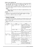
Page 5: ...ay counter with your unit Should any problem persist after you have made these check consult your nearest dealer Before going through the check list be first refer back to the connection operating procedures Symptom Cause Solution No power The car s ignition switch is If the power supply is con not on netted to the car s accessory circuits but the engine in not moving switch the ignition key to AC...

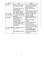
Page 6: ...microcomputer Remove the compact disc is operating incorrectly due then insert it again to noise Press the reset button The installation angle is Adjust the angle to less than greater than 30 30 The disc player is not Fasten the disc player installed correctly securely The compact disc is extreme Clean the compact disc try ly dirty or defective disc to play the new one Condensation Leave the disc ...

Page 7: ...bracket A then drill a 6 5 mm hole at each marked point 3 Mount the under dash side bracket A with screws 2 and nuts 3 4 Attach the rear bracket B to the back of the unit with the Hex Head Bolt with spring and flat washer 4 5 Bend the rear bracket B as needed to reach the firewall or other structural support and fix the rear bracket B with screw 2 and nut 3 or with tapping screw 5 and washer 6 NO ...

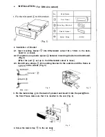
Page 8: ...ed use plastic spacer between mounting bracket and dashboard Fig 2 When the part set up to the DIN standard cutout is loose 2 3 Bend frame straps of mounting bracket to the outside until the frame is tightend in the cutout Fig 3 RACKET Side view Fig 2 Fig 3 3 Fix the metal strap to the back of product and insert it into the part from the front Please make sure that it is inserted to the end Fig 4 ...

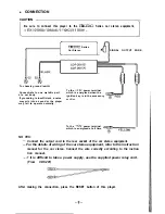
Page 9: ...y is in the accessory may mix into a sound or the player position may fail to operate normally To the 12V power terminal which is energized at all time NO TES Connect the output cord to the rear socket of the car stereo equipment For the details of wiring of the car stereo equipment refer to the instruction manual for the car stereo Connect the wire correctly according to the instruc tion manual I...

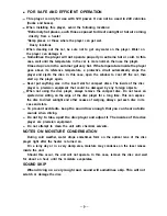
Page 10: ...r compact discs The inside of the disc player is precision equipment that could be damaged by any foreign objects When not using the disc player always remove the compact disc Do not leave an ejected disc sitting on the edge of the disc player for a long time This can expose the disc to direct sunlight and other causes of warping Always put each disc in its case and store To prevent accidents keep...

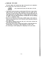
Page 11: ...icles Wipe in a straight motion from the inside to the outside of the disc Small dust particles and light stains will have absolutely no effect on reproduction quality Never use such chemicals as record sprays antistatic sprays or fluid benzine or thinner to clean compact discs Such chemicals would irreparably damage the disc s plastic surface Discs should be returned to their cases after use to a...

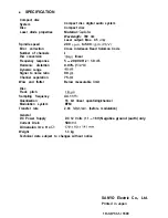
Page 12: ...B Harmonic distortion 0 03 1 kHz Dynamic range 90dB Signal to noise ratio 90 dB Channel separation 75 dB Wow and flutter Below measurable limit Disc Track pitch 1 6pm Sampling frequency 44 1 kHz Quantization 16 bit linear quantizing channel Modulation system EFM Transfer rate 2 03 Mbit set before modulation General DC Power Supply DC 12 Volts 11 16V Negative ground earth only Current Drain 500 mA ...

Reviews: