background image

A3

SCH_KR6AD

J10EG030G

K6L

1

1

2
3

3

J10EG030G

K6M

1

1

2
3

3

J10EG030G

K6J

1

1

2

3

3

AC CORD

1AV4M10B38300

FN904

1AV4M10B40900

FN902

1AV4M10B38300

FN903

1AV4M10B38300

FN901

J10EG031G

K8N

1

1

2
3

S10B7590N

SW902

1

2

J10EP030G

K8Q

1

1

2

3

3

B4A10B10300

SP901

1

2

J10EG030G

K8S

1

1

2
3

3

J10EZ120G

K8A

1

1

2

3

4

10

5

11

6

12

12

7

8

9

J10EZ050G

CN02

1

5

J10EZ050G

K8H

1

5

J10ES036G

K6S

1

2

3

J10EG065G

K8D

1

J10EP101G

K8R

1

1

2

3

4

5

6

7

8

9

10

10

(LIVE)

(NEUT)

F601

6.3A250VTS

275GM0.22VB

C602

;275GK0.22VBBC

;275GM0.22VCBC

275GM0.22VB

C601

;275GK0.22VBBC

;275GM0.22VCBC

J20B

00100

F601A

;B4J20B0010J

J20B

00100

F601B

;B4J20B0010J

MYG314K300

VA601

;DVXAVB007

1

2

J10EM024N

K6A

1

2

F35B1010N

T601

1

2

3

4

K6B_1A

K6A_1A

K6B_1B

K6A_1B

K6B_2B

K6A_2A

K6B_2A

K6A_2B

T601H1

T601H2

T601H3

T601H4

B4J10B0100N

K6B

1

2

1SJ240KLBYAS

R601

250KK

470XH

C603

250KK

470XH

C604

-5V(60mA)

F/B DET

P.F.CONTROL

(2.17A)

15.5V

1

S6V

<B-1K>

F/B DET

S6V

15.5V(MAX 2.85A)

6V(MAX 2.10A)

15.5V

5V(MAX 0.5A)

2

(60mA)

6V

-5VS

;CEXAVB00200

DHXAVB028---G

SFPL-52P

D631

;RF101L2SP

R61A

1SJ68KLBYBV

1

2

K6D_2B

KK1000GQ

C633

;KK1000LBYAG

1/3GJ47

R634

J10EM024N

K6D

1

2

6.3EM1000ZV

C694

;6.3EM1000LBVD

K6D_1B

T651H1

CJ330CGQ

C62J

;CJ330LBZBG

R61E

1SJ68KLBYBV

1

2

1/10GF

1.2KC

R62F

UDZS12BG

D633

;DZXLBXB12BG

;02DZ12YG

1/10GJ

4.7KC

R623

B4R3ZA102NN

VR611

1

2

3

K6D_1A

L612H1

AH

Q651

LAMPDC_ON

R61F

1SJ68KLBYBV

1

2

1SS

355

D62R

;1SS352G

;DDXLBB053G

X

R651

25KZ

0.1GQF

C62M

K6C_2A

1/10GJ

1KC

R657

C615_B

1/10GJ

100C

R62G

1/10GJ

220KC

R62T

1/10GJ

2.7KC

R647

1SS

355

D616

;1SS352G

;DDXLBB053G

1/10GF

6.2KC

R655

1/10GJ

560C

R606

X

D654

SFPB

-54P

D612

;RB160L

-40P

Z20051---

FB693

C615_A

F35B1450N

L611

1/10GJ

2.2MC

R62R

1/8GJ22

R62Q

;GJ22B

1/10GF

10KC

R653

CEXAVB

00500

C615

;CEXAVB00700

KK680GQ

C637

;KK680LBYAG

25KZ

0.1

GQF

C62D

1000KK

1000NH

C611

1/10GJ18KC

R641

1/2GJ240K

R615

450GK

0.1FD

C616

;450GK0.1DV

1/10GJ

820C

R656

X

Q652

Z20051---

FB695

DB611H1

K6C_1A

DB611H4

1/10GJ

10KC

R646

1/10

GJ

330C

R62H

1

2

D10XB60

DB611

1

1

2

2

3

3

4

4

KK0.068

GQ

C62F

;KK0.068LBYAG

PTH612

1/10GJ

390C

R62M

1/2GF

150K

R620

1/10GJ

1KC

R635

TLP421F-BL

PC641

1

2

3

4

FFXAVB

001SGJ

R631

1

2

1

IF

B

2

IIN-

3

VDET

4

OVP

5

VF

B

6

VIN

-

7

GND

8

OUT

9

VC

10

VC

C

11

CS

12

ON/OFF

13

RE

F

14

SYNC

15

CT

16

IDE

T

SFPL-52P

D653

;RF101L2SP

1/10GJ

68KC

R604

IC63_1

C639

35EM2205D

;35EM220LBVD

AJ

Q601

C615H1

2000KK

330NH

C634

1/10GJ

1KC

R658

IC631H

2HEA0310-

1 2

1/10GJ

2.4KC

R62L

1/10GJ2.4KC

R639

3/4JJ15

R633

1/3GJ

120

R636

16EM4708TL

C653

;16EM470LBVE

KZ0.01

GQF

C62I

;KZ0.01LBYDG

1/10GJ

4.7KC

R637

1/10GJ

15KC

R648

B4J10B0100N

K6C

1

2

L26B3470G

FB694

2SK2837

Q611

1

G

2

D

3

S

1/10GJ

9.1KC

R603

5XK0.075VBE

R611

1/10GJ

1KC

R659

J10AU105N

K6R

1

1

2

3

4

5

6

7

8

9

10

10

1/2GF

150K

R617

25EM22005D

C651

;25EM2200LBVE

1/10GJ

750C

R62E

16KZ

0.47GQF

C641

2000KK

220AHH

C635

L612H2

KK330GQ

C657

;KK330LBYAG

1/10GJ

470KC

R62C

T651H11

X

R652

Z20051---

FB611

10EM22004U

C652

;10EM2200LBVD

25KZ

0.1GQF

C654

1

VIN

3

GND

4

CT

5

CONT

6

CSS

7

CD

8

VCC

9

DRI

11

OC

12

OS

14

OUT

15

VB

KK

0.047

LZB

C62K

10EM1000ZV

C693

;10EM1000LBVD

1/10GF

560C

R654

K6C_2B

DHXAVB003

PTH611

450GK

1BS

C614

C652_1

C652_2

C639_2

1/10GJ

30KC

R62D

1SS

355

D619

;1SS352G

;DDXLBB053G

D611H1

K6D_2A

25KK4.7BB

C62R

35TM2.2DG

C631

1/2GF

150K

R618

1/10

GJ

10KC

R62B

R61B

1SJ68KLBYBV

1

2

25KZ

0.1GQF

C605

KZ0.22FA

C643

AJ

Q622

KK330GQ

C658

;KK330LBYAG

CRF03P

D636

1/10

GJ

47KC

R62P

1/10GJ

4.7C

R62I

1

2

T651H6

1/10GJ

1.5KC

R62A

K6C_1B

C615H2

KK470GQ

C62B

;KK470LBYAG

C639_1

D611H2

AH

Q602

10KK

0.33GQ

C62C

1SS

355

D617

;1SS352G

;DDXLBB053G

450GK

1BS

C613

1/10GJ

4.7KC

R660

X

C695

1/10GJ

1.2KC

R607

1/10

GJ

180C

R62J

25KZ

0.1GQF

C62E

2SK3934

Q643

C651_1

1/2GJ240K

R616

DB611H3

KZ0.1FA

C636

10KK

0.47

LZB

C656

LAMPDC_ON

16KK4.7BA

C644

TLP421F-BL

PC643

1

2

3

4

CJ68

CGQ

C62A

;CJ68LBZBG

630NJ

0.022

EAQ

C642

;630NJ0.022LBZA

25KZ

0.1GQF

C62T

L51B6620N

T651

;L51B6800N

2

3

5

6

7

8

10

9

11

4

1

1/2GF

150K

R619

AH

Q642

C651_2

25TM1FD

C638

;25TM1DR

;25TM1JR

AH

Q621

25KZ

0.1GQF

C640

25EM1000ZV

C659

;25EM1000LBVE

L26B5081N

L612

;L26B5371N

1

2

DB611H2

25KZ

0.1GQF

C655

25KZ

0.1GQF

C660

FML-G16S

D611

T651H5

Z20051---

FB613

1000KK

1000NH

C612

1SS

355

D618

;1SS352G

;DDXLBB053G

DB611AH1

1/8GZ000

R62Z

;GZ0B

1

2

FMB-26L

D652

;RB085T-60

3

1

2

FMB-26L

D651

;RB085T-60

3

1

2

J10AU035N

K690

1

3

K690_2

CO

M

NO

NC

S10B6510N

SW901

1

2

3

K690_3

K690_1

SCREW_14

X

SCR1

1 2

3

4

5 6

7

8 9 10 11 12 13 14

SCREW_14

X

SCR2

1 2

3

4

5 6

7

8 9 10 11 12 13 14

R/C PRE AMP

1/16GZ0A

R2901

J10EG065G

K29D

1

4

6

S5V

KK470MN

C2902

;KK470AXH

;KK470AYH

10KZ1MNF

C2901

;10KZ1AY

1/16GJ100A

R2903

6.3KZ47ME

C2903

U20C01800

A2901

1

2

3

1/16GJ10

A

R8832

1/16GJ10

A

R8831

CJ33DAY

C8831

;CJ33DAX

;CJ33CM

CJ33DAY

C8832

;CJ33DAX

;CJ33CM

1

1

SDA

2

SCL

3

O.S.

4

GND

5

INT OUT

6

A1

7

A0

8

+VS

X

R8834

25KZ0.1MNF

C8833

;25KZ0.1AY

1/10GZ0C

R8833

S5V

X

SC8831

1

2

A901

AC100-120V

AC200-240V

K5R
J11UC300G

1

30

30

1

30

1

LP901

METAL HALIDE LAMP

G/R-PNL

K5G
J11UC300G

K5B
J11UC300G

B-PNL

SIDE

1

30

30

1

1

30

FAN

CONT

B

FAN

CONT

A

PROJECTION LENS

LF901
U20B30103

(LIVE)

(NEUT)

F.G.

SCEL

GND

RXL

TXL

200W

CN01

380V

1

3

RXL
GND

SCEL

TXL

PHILIPS

FSP-

N.C.

FSP+

FOR SANYO SP

TO CONTROL UNIT

5V

5V

FRONT

TO MICRO-SW

(TO K690)

POWER

EXT

EXT

15.5V

S6V

-5V

LAMP_DC_ON

LAMP_DC_ON

GND

GND

GND

GND

GND

GND

S6V

FILTER

MSW

LAMP

BALLAST

MAIN

COLD

POWER

R/C

HOT

IC621

FA5502M

S6V

S-5V

15.5V

LAMPDC_ON

Power Supply

R

LCD

PANEL

G

LCD

PANEL

B

LCD

PANEL

IC631

STR-Z2156A

IC651

UPC1093T

LM76CHMX-5P

IC8831

TEMP SENSOR 3

  (OUTSIDE)

POWER FACTOR CORRECTION

1

2

3

4

5

6

7

8

9

10

11

12

13

14

15

16 

A

B

C

D

E

F

G

H

I

J

K

L

A

B

C

D

E

F

G

H

I

J

K

L

KR6AD-01

TERMOSTAT_SW

(SET TO OPEN
AT 105°C)

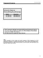
Schematic Diagrams

cAutIoN

Components indicated by a mark 

!

 in this schematic diagram have the special sig-

nificance in the safety. It is therefore, particularly recommended that the replacement 
of those parts must be made by exactly the same parts.Must be used with a specified 
fuse. Unauthorized substitutions may result in fire or accident.
This  projector  is  isolated  from  AC  line  by  using  the  internal  converter  transformer. 
Please pay attention to the following notes in servicing.
1.  Do not touch the part on hot side (primary circuit) or both parts on the hot and cold 

sides (secondary circuit) at the same time.

. Do not shorten the circuit between hot and cold sides.
3.  The grounding lead must be connected to the ground of the same circuit when mea-

suring the voltages and waveform.

cAutIoN

Fuse of the specified parts number must be used.
Unauthorized substitutions may result in fire or accident.

Summary of Contents for 1 122 356 20

Page 1: ...E NO SM5110860 00 FILE NO Model No PLC XW55A PLC XW50A U S A Canada Europe U K Asia Chassis No KR6 XW55A00 KP6 XW50A00 Match the Chassis No on the unit s back cover with the Chassis No in the Service Manual If the Original Version Service Manual Chassis No does not match the unit s additional Service Literature is re quired You must refer to Notices to the Original Service Manual prior to servicin...

Page 2: ...nu Operation 24 Memory IC IC1371 Replacement 24 Circuit Adjustments 25 Test Points and Locations 28 Service Adjustment Data Table 29 Chassis Block Diagrams 41 Chassis over view 41 System control 42 Power supply protection circuit 43 Fan control circuit 44 Troubleshooting 45 Indicators and Projector Condition 45 No Power 46 No Picture 47 No Sound 48 Control Port Functions 49 System Control I O Port...

Page 3: ...ore replacing the cabinet cover thoroughly inspect the inside of the cabinet to see that no stray parts or tools have been left inside Before returning any projector to the customer the service personnel must be sure it is completely safe to operate without danger of electric shock Service Personnel Warning Eye damage may result from directly viewing the light produced by the Lamp used in this equ...

Page 4: ...Lamp 200W Interface Video Input Jack RCA Type x 1 Audio Input Jacks RCA Type x 2 Computer Component S Viideo Input Terminal Anlaog RGB Mini D sub 15 pin Terminal x 1 Monitor Output Terminal Anlaog RGB Mini D sub 15 pin Terminal x 1 Computer Component Audio Input Jack Mini Jack stereo x 1 Service Port Connector Mini DIN 8 pin x 1 Audio Output Jack Mini Jack stereo x 1 Variable Audio Internal Audio ...

Page 5: ...projector can not turn on Thermal switch There is the thermal switch SW902 inside of the projector to detect the internal temperature rising abnormally When the internal tem perature reaches near 105 C the thermal switch opens to stop the operation of the power supply circuit The thermal switch cannot be reset itself automatically even if the internal temperature becomes normal Reset the thermal s...

Page 6: ...dust from accumulating on the optical elements inside the projector Should the air filters become clogged with dust particles it will reduce cooling fans effectiveness and may result in internal heat build up and ad versely affect the life of the projector Clean the air filters following the steps below 1 Turn off the projector and disconnect the AC power cord from the AC outlet 2 Turn over the pr...

Page 7: ... power cord into an AC outlet again Keep pressing the SELECT button until the POWER indicator lights continuously This is complete the resetting of the security function The PIN code lock and Logo PIN code lock are reset as the initial PIN code at the factory and the Key lock function is disabled Please refer to the owner s manual for further information of the security functions Function Descript...

Page 8: ... Replace the lamp cover and tighten the screw 5 Connect the AC cord to the projector and turn on 6 Reset the lamp replacement counter see below explanation Note The projector cannot be turned on with lamp cover removed because when the lamp cover is removed the lamp cover switch is also re leased to switch off the lamp circuit How to reset Lamp Replace Counter 1 Turn the projector on press the MEN...

Page 9: ...Following steps show the basic procedures therefore unnecessary step may be ignored Caution The parts and screws should be placed exactly the same position as the original otherwise it may cause loss of performance and product safety Screws Expression Type Diameter x Length mm T type M Type M3x8 Control Buttons R C Board Fig 1 M3x8 x5 ...

Page 10: ... 10 x Main Board Filter Board removal Mechanical Disassembly Main board AV Panel M2 5x6 x6 T3x8 Fig 2 Filter Board T3x6 x2 M3x6 T3x6 Shield Plate M3x6 ...

Page 11: ...anical Disassembly c Power Board Ballast Board Thermal Sw SW902 Fan FN902 removal Fig 3 Power board Ballast board Isolation sheet Ballast socket Thermal switch SW902 M3x8 T3x8 x2 T3x6 x2 T3x8 T3x6 x2 T3x8 FN902 ...

Page 12: ... 12 Mechanical Disassembly Fig 4 v Optical Unit Fan FN901 removal Optical unit Air Duct FN901 T3x8 x2 T3x8 x2 T3x8 x6 ...

Page 13: ... 13 Mechanical Disassembly Fig 5 b Fans FN903 FN904 Speaker Noise Filter MSW Board removal Noise Filter Spacer FN904 T3x6 x4 T3x12 x4 Black T3x8 T3x8 T3x8 x2 MSW Board FN903 Speaker ...

Page 14: ... and Main Board following to the Mechanical Disas sembly Disassembly requires a 2 0mm hex wrench z Integrator lens in disassembly Hooks Integrator lens in Integrator Lens In Ass y M2 5x5 x2 Fig 1 Rugged surface Behind x Relay lens disassembly Relay lens Relay lens Ass y M2 5x5 x2 Fig 2 Spring ...

Page 15: ...cal Pats Disassembly c Polarized glass in disassembly Polarized glass Polarized glass in Ass y M2 5x5 x1 Fig 3 Film side LCD Panel Prism Ass y Fig 4 1 v LCD Panel Prism Ass y removal M2 5x4 x2 M3x10 Bottom side ...

Page 16: ...ite uniformity on the screen If you find the color shading at the some part of the screen it needs to take the color shading adjustment This adjustment should be performed by a computer and it also requires a special software Color Shading Correction The software will be supplied separately and can be ordered as follows COLOR SHADING CORRECTION Ver 4 00 Service Parts No 645 075 9611 Panel Type Che...

Page 17: ...Mount the polarized glasses as the film attached side comes to the LCD panel side M2x2 M2x2 Film Blue Red Green Pre Polarized Glass B Fig 5 n Projection lens removal M2 5x8 x4 Projection lens Polarized Glass B Before removing the Projection Lens it is required to remove the Optical Unit from the cabinet bottom Fig 6 ...

Page 18: ... 18 Optical Parts Disassembly m Optical Unit Top removal M3x8 x5 Optical top Fig 7 ...

Page 19: ...ions Direction of Integrator lens out PLC XW55A Rugged surface is facing to the PBS side PLC XW50A Rugged surface is facing to the lamp side The printed part no comes to this side The printed part no comes to this side No Parts Name 1 Integrator lens OUT 2 Prism beam splitter PBS 3 Condenser lens OUT 4 Dichroic mirror B 5 Dichroic mirror G 6 Condenser lens G 7 Relay Lens IN 8 Mirror R 9 Condenser ...

Page 20: ...t adjustment B Contrast adjustment Integrator lens adjustment Relay lens out adjustment Electrical Adjustments Panel type check and setting Fan control adjustment Pedestal adjustment PC Gain adjustment PC Pedestal adjustment 1080i Gain adjustment 1080i Gain adjustment Video Black reference adjustment Common center adjustment 50 white adjustment PC White balance adjustment PC 50 white adjustment Vi...

Page 21: ...g optical adjustments below remove the Cabinet Top following to the Mechanical Disassembly Adjustments require a 2 0mm hex wrench and a slot screwdriver When you adjust Integrator lens or Relay lens adjustment you need to disconnect FPC cables of LCD panels on the main board Optical adjustment requires a 2 0mm hex wrench and a slot screwdriver Note Do not disconnect connectors on the main board be...

Page 22: ...een as shown in Fig 2 1 loosen 1 screw A and adjust the slot B to make color uniformity in white by using a slot screwdriver 2 If the shading appears on the top or bottom of the screen as shown in Fig 2 2 loosen 2 screws C and adjust the slots D to make color uniformity in white by using a slot screwdriver 4 Tighten screws A and C to fix the Integrator lens unit Note The relay lens adjustment must...

Page 23: ...ust the adjustment base of relay lens assy to make color unifor mity in white If the shading appears on the left or right of the screen as shown in Fig 3 loosen 1 screw A and adjust the slot B to make color unifor mity in white by using a slot screwdriver 4 Tighten the screws A to fix the relay lens unit Relay lens Out adjustment Optical Adjustments ...

Page 24: ...t counter is stored in the Memory IC Please note that the lamp replace counter will be reset when the memory IC is replaced Lamp replace counter cannot be set to the previous value Caution to memory IC replacement When memory IC is replaced with new one the CPU writes down the default data of the service adjustments to the replaced IC as the mentioned on the service ad justment table As these data...

Page 25: ... to pins 1 and 3 of K6D 2 Adjust the voltage by using VR611 as following AC Input Reading 230V 380V 2V Caution Be sure to connect the lamp when taking this adjustment This adjustment is not required even if the power board is replaced because this adjustment is carried out be fore parts shipment Output Voltage adjustment Before setting you need to check which type of LCD pan el is placed on the pr...

Page 26: ...int TPR1 and chassis ground 6 Select item no 125 and change data value to adjust amplitude a to be 10 0 0 1V 7 Connect an oscilloscope to test point TPB1 and chassis ground 8 Select item no 126 and change data value to adjust amplitude a to be 10 0 0 1V a black level black level n Black Reference adjustment 1 Enter the service mode 2 Receive the 16 step grey scale computer signal with Computer1 RG...

Page 27: ...ode 2 Enter the service mode 3 Connect an oscilloscope to test point TPG1 and chassis ground 4 Select group no 100 item no 6 and change data value to adjust amplitude a to be 1 6 0 1V a white level white level 50 White adjustment PC 1 Receive the 16 step grey scale composite video sig nal with Video mode 2 Enter the service mode 3 Connect an oscilloscope to test point TPG1 and chassis ground 4 Sel...

Page 28: ... 28 K5B K5R K5G K6J K6L K6M K6S K8A K8D K8H K8N K8S K8Z IC401 IC801 IC301 TPFANB TPFANA TPB1 TPG1 TPR1 Electrical Adjustments MAIN BOARD Test Points and Locations ...

Page 29: ... 120 PreCoast PC Video 480i 7 0 63 121 PostCoast PC Video 480i 13 0 63 122 PreCoast PC Video 575i 7 0 63 123 PostCoast PC Video 575i 13 0 63 124 PreCoast PC Video 480p 7 0 63 125 PostCoast PC Video 480p 13 0 63 126 PreCoast PC Video 575p 7 0 63 127 PostCoast PC Video 575p 13 0 63 128 PreCoast PC Video 720p 60Hz 7 0 63 129 PostCoast PC Video 720p 60Hz 13 0 63 130 PreCoast PC Video 720p 50Hz 7 0 63 ...

Page 30: ...P Mode Sets for IP Off 1 0 1 0 IP Block not used 1 IP OFF used with IP Block 1 3 2 PullDown Mode 1 1 3 bit0 Global Motion bit1 Video Motion 2 Detect Film Mode Enable 0 0 2 0 2 3pull down 2 2pull down 1 2 3pull down 2 2 2pull down 3 Force IP Mode 2 0 2 0 IP Process Disable 1 Force Normal IP Mode 2 Force Film Mode Effective only for PSF Signal Group 41 Deinterlacer setting Effective only for Progres...

Page 31: ...Min 0 Brightness Max 1023 Min 0 Color Max 1023 Min 0 Tint Max 180 Min 0 Sharpness Max 57 Min 0 1 Center Brightness 512 480 512 500 512 512 0 1023 2 Center Color 512 534 512 512 512 512 0 1023 3 Center Tint 90 90 90 90 90 90 0 180 4 Center Sharpness 16 16 16 16 16 16 7 49 5 Alpha Contrast 40 40 40 40 40 40 0 1000 6 Alpha Brightness 140 140 140 140 140 140 0 1000 7 Alpha Color 70 70 70 70 70 70 0 10...

Page 32: ...ing 7 7 0 255 56 V Line Shading Comp Value Setting G1 Normal Mount Rear Ceiling 3 3 0 255 57 V Line Shading Comp Value Setting G2 Normal Mount Rear Ceiling 1 2 0 255 58 V Line Shading Comp Value Setting G3 Normal Mount Rear Ceiling 0 1 0 255 59 V Line Shading Comp Value Setting G4 Normal Mount Rear Ceiling 253 253 0 255 60 V Line Shading Comp Value Setting B0 Normal Mount Rear Ceiling 7 7 0 255 61...

Page 33: ...L3E06100 95 0 511 Common Center Adjustment 130 SyncPosition 0 0 1 Link with 130 and 131 131 SyncVideoPosition 0 0 1 132 Color Shading SW 1 0 1 133 V Line Shading Comp Value Setting R1 dot Normal Mount Rear Ceiling 18 16 0 31 Center value is 16 134 V Line Shading Comp Value Setting R2 dot Normal Mount Rear Ceiling 16 16 0 31 135 V Line Shading Comp Value Setting R3 dot Normal Mount Rear Ceiling 16 ...

Page 34: ...0 255 Read only 55 Motor Disable 0 On 1 Off 0 0 1 56 Menu Position Move menu X asis 0 0 1024 57 Menu Position Move menu Y asis 0 0 1024 60 Spread Spectrum Enable 1 0 1 0 Off 1 On 61 Spread Spectrum Frequency 80 0 500 62 Spread Spectrum Amplitude 100 0 300 Group 201 Option signal 0 FrameLock Option 0 0 1 0 FrameLockOFF at PC signal 1 FrameLockON at PC signal and 47Hz Vfreq Panel frequency of input ...

Page 35: ...00 100 100 0 100 Memorized 4 FAN_TEMP_C A_WARNING Temperature C A to judge the Temp Failure Filter Cloggled 100 100 100 100 100 100 100 100 0 100 Memorized 5 FAN__SPEED_MONI Fan Speed Monitor Read only 6 FAN__SPEED_MONI Fan Speed Monitor Read only 7 FAN_TEMP_A_MONI Temp Sensor Monitor Read only 8 FAN_TEMP_B_MONI Temp Sensor Monitor Read only 9 FAN_TEMP_C_MONI Temp Sensor Monitor Read only 10 Lamp ...

Page 36: ... FAN1 Control Min Value in High land Normal 135 131 0 255 63 HINOR_VALU_FAN1_MAX FAN1 Control MaxValue in High land Normal 135 131 0 255 64 HINOR_VALU_FAN2_MIN FAN2 Control Min Value in High land Normal 130 130 0 255 65 HINOR_VALU_FAN2_MAX FAN2 Control MaxValue in High land Normal 130 130 0 255 66 HIECO_TEMP_FAN1_MIN FAN1 Control Start Temperature in High land Eco 30 30 0 255 67 HIECO_TEMP_FAN1_MA...

Page 37: ...emp Up Time Normal Ceil 0 0 120 Temp Up Time Eco Ceil 0 0 121 Standby Cooling Check Cycle 5 5 122 Standby Cooling Start Threshold 54 54 123 SAfter Shutdown Cooling 1 1 0 No 1 Yes 124 OnStart Cooling Start Threshold 38 38 0 100 Group 260 Auto Calibration Commn Auto Calibration 0 Execute Calibration 0 0 1 Executes Auto Calibration when changiing the Value PC White 100 1 Loop Count Maximum Execution ...

Page 38: ...cy Threshold 5 0 10 0 10 Not matched 3 Fine Phase Do Phase Adj after Total Dot Adj 1 0 1 0 Executes Fine Phase 1 Not Execute 4 BLKDET Black Level Detection Area 1 0 3 5 PHASEMSK Phase Detection Filter 0 0 3 0 Effective All Bit 1 Disable Lower 1 bit 2 Disable Lower 2 bit 3 Disable Lower 3 bit Group 290 PanelType PanelType Check 0 GammaL R View Current Setting Check 0 0 20 0 Gamma for L Turn 20 Gamm...

Page 39: ...95 4 Disp Line 700 0 4095 Group 526 YCbCr 1080i 60 0 Total Dots 2200 0 4095 Read only 1 Disp Dots 1872 0 4095 2 H Back Porch 258 0 4095 3 V Back Porch 54 0 4095 4 Disp Line 1052 0 4095 Group 527 YCbCr 1080i 50 0 Total Dots 2640 0 4095 Read only 1 Disp Dots 1870 0 4095 2 H Back Porch 258 0 4095 3 V Back Porch 54 0 4095 4 Disp Line 1052 0 4095 Group 528 YCbCr 1035i 0 Total Dots 2200 0 4095 Read only...

Page 40: ...Total Dots 1980 0 4095 1 Disp Dots 1246 0 4095 2 H Back Porch 310 0 4095 3 V Back Porch 34 0 4095 4 Disp Line 702 0 4095 5 Clamp 1 0 255 6 Clamp Width 31 0 255 Group 546 RGBVideo 1080i 60 0 Total Dots 2200 0 4095 1 Disp Dots 1872 0 4095 2 H Back Porch 254 0 4095 3 V Back Porch 56 0 4095 4 Disp Line 1052 0 4095 5 Clamp 1 0 255 6 Clamp Width 31 0 255 Group 547 RGBVideo 1080i 50 0 Total Dots 2200 0 4...

Page 41: ...LK DB 0 7 DG 0 7 DR 0 7 A 1 23 D 0 15 288 206 204 142 143 78 331 161 6 1 21 10 5 8 10 10 12 214 124 388 TXD RXD TXD1 RXD1 R C IRRCVR0 4 27 1 30 9 22 4 82 260 258 265 264 262 2 5 13 7 13 SP901 SPEAKER L R VIDEO L R L R RGB H V RGB H V TPB1 B G R HS VS IC531 G D A S H L3E06100 IC561 R D A S H L3E06100 IC3801 RS232C DRIVER SP232 IC891 INVERTER TPG1 TPR1 Q1003 Q2031 R G B S_CHROMA S_Y VIDEO Q1004 Q100...

Page 42: ...D BLAST_AC BLAST_AC FAN_ERR TEMP_LED ON_33V ON_150V 346 111 184 11 LAMP_DET 90 201 LAMP_LED ON_50V 269 110 P_FAIL FAN_SW1 FAN_SW1 LAMP_DC_ON READY_LED 215 285 363 91 CHO_TXD CHO_RXD CHO_TXD CHO_RXD MUTE KEY1 295 26 347 28 KEY2 126 KEY3 IRRCVR0 IRRCVR0 SCL1 SDA1 SCL2 SDA2 216 214 211 294 SCL0 SDA0 283 212 290 208 IC301 SYSTEM CONTROL Q6843 Q6844 D6831 D6832 D6833 Q5036 Q6841 LAMP REPLACE WARNING PO...

Page 43: ...SW Power On L P Fail L PC643 IC631 POWER OSC STR Z2156 Feedback S6V 15 5V S 5V ON_150V LAMP_DC_ON IC4891 NAND S6V S16V S 5V 1 3 4 7 IC8811 TEMP SENSOR2 LM76CHMX LAMP PANEL OUT SIDE IC8821 TEMP SENSOR1 LM76CHMX IC8831 TEMP SENSOR3 LM76CHMX 26 LAMP_DET 90 2 13 295 215 11 201 ON_50V 110 LAMP_DC_ON 363 Power On H DC_ON 278 111 294 211 SCL1 SDA1 IC9882 INVERTER SW901 9V_AUDIO S16V DDC DDC FAN_A Q7812 D...

Page 44: ...D3614 D3626 IC8821 TEMP SENSOR1 LM76CH 2 1 IC8811 TEMP SENSOR2 LM76CH IC8831 TEMP SENSOR3 LM76CH MAIN BOARD IC301 SYSTEM CONTROL FAN_CON_B FAN_CON_A Power On H IC3531 D A M62398 IC4891 NAND 13 1 2 4 12 3 2 215 285 284 211 SCL1 SDA1 SCL1_S5 SDA1_S5 IC1302 208 290 SCL2 SDA2 SCL2_5 SDA2_5 IC1303 Power Error On P_Fail H SIGNAL MODE POWER ON STAND BY H L NORMAL ERROR H L FAN_SW1 P_FAIL P_FAIL FAN_ERR T...

Page 45: ...nnot be turned on until cool ing is completed Q The projector is ready to be turned on with the POWER ON OFF button Q The projector is operating normally Q The projector is in the Power management mode Q The temperature inside the projector is abnormally high The pro jector cannot be turned on When the projector is cooled down enough and the temperature returns to normal the POWER indi cator emits...

Page 46: ... via IC4891 and SW901 lamp cover switch to stop operation of the lamp circuit An abnormality occurs on the secondary power supply Check power supplies 15 5V S6V S 5V P_FAIL signal becomes Low when the abnormality occurs on any of the power supply lines An abnormality occurs on the fan control circuit Check FN901 FN902 FN903 FN904 and peripheral circuit If any of the fans has an error the fan lock ...

Page 47: ...s applied to pin 82 of IC301 System Control G sig nal is applied to pin 260 and B signal is applied to pin 258 of IC 301 HV sync signals are applied to pins 331 and 161 of IC301 System Control as the HS and VS signals S Video source Check S video signal Y C S_CHROMA signal is applied to pin 265 of IC301 System Con trol and S_Y signal is applied on pin 264 of IC301 Component video source The compon...

Page 48: ...eck speaker connection of the terminal K8F Yes No Check following steps Check IC5031 5V_AUDIO and peripheral circuit Check the Mute signal at pin 1 of IC5031 The Mute signal is output from pin 347 of IC 301 System Control The OUT_DET signal is sent from Audio Out terminal Mute On H at pin 347 of IC301 L at pin1 of IC5031 Check if the audio sig nal is observed at pins 5 and 8 of IC5031 Yes No ...

Page 49: ...L I 126 D25 ADC2 ADC2 KEY 2 Key Control Input I 29 D26 ADC6 ADC6 LAMP Option Lamp Option I 362 E14 PORTC4 GPIO PortC 4 IRM_RST 363 E15 PORTC0 GPIO PortC 0 LAMP_DC_ON Lamp Control Power Control On H O 367 E19 THRWSC 3 Wire Serial Clock SCLK Serial Control Clock O 368 E20 RXD0 UART 1 Receiver RXD_PW Serial Control RXD I 370 E22 ADC5 ADC5 Resolution Option Option Switch XGA SVGA I 216 E24 ADC3 ADC3 K...

Page 50: ...used 381 T22 MCKFBKN Memory Feedback Clock 138 T25 MCKN Memory Clock 41 T26 MCK Memory Clock 85 U1 BMUXIN2 Blue MUX input Ch2 not used 283 U3 SMUXIN1 SOG MUX input Ch1 SOG Sync on Green Signal Input I 409 U5 SMUXIN0 SOG MUX input Ch0 Y Y Signal Input I 282 V3 BMUXIN1 Blue MUX input Ch1 VIDEO Video Signal Input I 408 V5 BMUXIN0 Blue MUX input Ch0 not used 140 V25 MREFIN1 Memory Voltage Reference 82...

Page 51: ... 51 Waveform VIDEO signal VIDEO HSYNC signal HS VSYNC signal VS HSYNC signal GHS VSYNC signal HVS R S H signal TPR1 G S H signal TPG1 B S H signal TPB1 ...

Page 52: ... air spray disassemble and clean the optical unit Disassembly Cleaning Disassembly cleaning method should only be performed when the unit is considerable dirty and cannot be suf ficiently cleaned by air spraying alone Be sure to readjust the optical system after perform ing disassembly cleaning 1 Remove the cabinet top and main units following to Mechanical Disassemblies 2 Remove the optical base ...

Page 53: ... 53 IC Block Diagrams FA5502 P F Control IC621 L3E6100D D A S H LCD Driver IC501 IC531 IC561 ...

Page 54: ... 54 IC Block Diagrams L3E07072 LCD Driver Gamma Correction IC401 M62393 DAC IC3531 ...

Page 55: ... 55 IC Block Diagrams NJW1141 Audio Control IC5001 ...

Page 56: ...ized Composite STYRENE Styrene TA SOLID Tantalum Oxide Solid Electrolytic AL SOLID Aluminium Solid Electrolytic ELECT Aluminum Foil Electrolytic NP ELECT Non polarised Electrolytic OS SOLID Aluminium Solid with Organic Semiconductive Electrolytic POS SOLID Polymerized Organic Semiconductive DL ELECT Double Layered Electrolytic PPS FILM Polyphenylene Sulfide Film MT PPS FILM Metalized Polyphenylene...

Page 57: ... Location Assemblied Boards SW902 Thermal Switch FN904 Cooling Fan MSW Board Filter Board A901 Ballast Board R C Board FN902 Cooling Fan LP900 Lamp Ass y LF901 Noise Filter Power Board FN901 Cooling Fan Out Of Circuit Board Main Board SP901 Speaker FN903 Cooling Fan ...

Page 58: ...305 015 8727 TR 2SC2812 L6 TB 305 015 8925 TR 2SC2812 L7 TB 305 163 1615 TR 2SC2812N L6 TB0 305 173 9816 TR 2SC3928A1R 305 173 9915 TR 2SC3928A1S Q1004 305 014 4512 TR 2SC2412K T146 R 305 014 4611 TR 2SC2412K T146 S 305 015 8727 TR 2SC2812 L6 TB 305 015 8925 TR 2SC2812 L7 TB 305 163 1615 TR 2SC2812N L6 TB0 305 173 9816 TR 2SC3928A1R 305 173 9915 TR 2SC3928A1S Q1006 305 014 4512 TR 2SC2412K T146 R ...

Page 59: ...15 TR 2SC2812N L6 TB0 305 173 9816 TR 2SC3928A1R 305 173 9915 TR 2SC3928A1S Q5064 305 014 4512 TR 2SC2412K T146 R 305 014 4611 TR 2SC2412K T146 S 305 015 8727 TR 2SC2812 L6 TB 305 015 8925 TR 2SC2812 L7 TB 305 163 1615 TR 2SC2812N L6 TB0 305 173 9816 TR 2SC3928A1R 305 173 9915 TR 2SC3928A1S Q5081 305 014 4512 TR 2SC2412K T146 R 305 014 4611 TR 2SC2412K T146 S 305 015 8727 TR 2SC2812 L6 TB 305 015 ...

Page 60: ...16 TR 2SC3928A1R 305 173 9915 TR 2SC3928A1S Q6861 305 134 5928 TR 2SA1037AK T146 R 305 147 2218 TR 2SA1037AK S T146 305 002 0311 TR 2SA1037K T146 R 305 002 0410 TR 2SA1037K T146 S 305 002 6729 TR 2SA1179 M6 TB 305 002 6927 TR 2SA1179 M7 TB 305 163 1516 TR 2SA1179N M6 TB 305 173 9618 TR 2SA1235A1E 305 173 9717 TR 2SA1235A1F Q6862 305 014 4512 TR 2SC2412K T146 R 305 014 4611 TR 2SC2412K T146 S 305 0...

Page 61: ...303 454 0514 CERAMIC 0 1U Z 25V 303 343 3718 CERAMIC 0 1U Z 25V C2523 403 461 3710 CERAMIC 0 1U Z 25V 303 454 0514 CERAMIC 0 1U Z 25V 303 343 3718 CERAMIC 0 1U Z 25V C2524 303 379 6714 CERAMIC 10U K 16V C2526 303 401 4312 ELECT 47U M 25V 303 419 5219 ELECT 47 0UM 25V C2527 403 461 3710 CERAMIC 0 1U Z 25V 303 454 0514 CERAMIC 0 1U Z 25V 303 343 3718 CERAMIC 0 1U Z 25V C2531 403 461 3710 CERAMIC 0 1...

Page 62: ...C 0 1U Z 25V 303 454 0514 CERAMIC 0 1U Z 25V 303 343 3718 CERAMIC 0 1U Z 25V C334 403 461 3710 CERAMIC 0 1U Z 25V 303 454 0514 CERAMIC 0 1U Z 25V 303 343 3718 CERAMIC 0 1U Z 25V C335 403 461 3710 CERAMIC 0 1U Z 25V 303 454 0514 CERAMIC 0 1U Z 25V 303 343 3718 CERAMIC 0 1U Z 25V C336 403 461 3710 CERAMIC 0 1U Z 25V 303 454 0514 CERAMIC 0 1U Z 25V 303 343 3718 CERAMIC 0 1U Z 25V C337 403 461 3710 CE...

Page 63: ...5V 303 343 3718 CERAMIC 0 1U Z 25V C378 403 461 3710 CERAMIC 0 1U Z 25V 303 454 0514 CERAMIC 0 1U Z 25V 303 343 3718 CERAMIC 0 1U Z 25V C379 403 461 3710 CERAMIC 0 1U Z 25V 303 454 0514 CERAMIC 0 1U Z 25V 303 343 3718 CERAMIC 0 1U Z 25V C3801 303 439 8412 CERAMIC 2 2U M 6 3V C3802 303 439 8412 CERAMIC 2 2U M 6 3V C3803 303 439 8412 CERAMIC 2 2U M 6 3V C3804 303 439 8412 CERAMIC 2 2U M 6 3V C3806 3...

Page 64: ...05 303 381 5316 ELECT 100U M 16V 303 369 3211 ELECT 100U M 16V C506 303 453 8917 CERAMIC 0 1U K 16V 303 453 8610 CERAMIC 0 1U K 16V C5061 303 391 5511 ELECT 10U M 16V 303 175 7212 ELECT 10U M 16V C5069 303 391 5511 ELECT 10U M 16V 303 175 7212 ELECT 10U M 16V C508 303 453 8917 CERAMIC 0 1U K 16V 303 453 8610 CERAMIC 0 1U K 16V C5081 303 379 6714 CERAMIC 10U K 16V C5083 303 394 1312 ELECT 100U M 6 ...

Page 65: ...ECT 100U M 6 3V C564 303 453 8917 CERAMIC 0 1U K 16V 303 453 8610 CERAMIC 0 1U K 16V C5642 403 461 3710 CERAMIC 0 1U Z 25V 303 454 0514 CERAMIC 0 1U Z 25V 303 343 3718 CERAMIC 0 1U Z 25V C5643 303 391 5115 ELECT 100U M 16V 303 296 9515 ELECT 100U M 16V C566 303 453 8917 CERAMIC 0 1U K 16V 303 453 8610 CERAMIC 0 1U K 16V C5662 403 461 3710 CERAMIC 0 1U Z 25V 303 454 0514 CERAMIC 0 1U Z 25V 303 343 ...

Page 66: ...MT GLAZE 12K JA 1 16W R1368 301 224 9019 MT GLAZE 10K JA 1 16W R1371 301 225 0213 MT GLAZE 3 3K JA 1 16W R1372 301 299 2410 MT GLAZE 5 6K FA 1 16W R1373 301 299 2410 MT GLAZE 5 6K FA 1 16W R1374 301 294 3016 MT GLAZE 10K FA 1 16W R1376 301 253 3712 MT GLAZE 0 000 ZA 1 4W 301 035 4111 MT GLAZE 0 000 ZA 1 8W R1401 301 225 8110 MT GLAZE 10 JA 1 16W R1402 301 225 8110 MT GLAZE 10 JA 1 16W R1403 301 22...

Page 67: ... 10 JA 1 16W R3532 301 225 8110 MT GLAZE 10 JA 1 16W R356 301 226 1516 MT GLAZE 0 000 ZA 1 16W R357 301 226 1516 MT GLAZE 0 000 ZA 1 16W R3581 301 224 9316 MT GLAZE 1K JA 1 16W R3582 301 225 1210 MT GLAZE 4 7K JA 1 16W R3583 301 225 1210 MT GLAZE 4 7K JA 1 16W R3584 301 225 3818 MT GLAZE 1 5K JA 1 16W R3601 301 225 8516 MT GLAZE 1 8K JA 1 16W R3602 301 225 0619 MT GLAZE 5 6K JA 1 16W R361 301 256 ...

Page 68: ...3 MT GLAZE 15K FA 1 16W R554 301 302 3410 MT GLAZE 13K JA 1 16W R555 301 229 7218 MT GLAZE 18K JA 1 16W R559 301 299 2410 MT GLAZE 5 6K FA 1 16W R5631 301 224 8814 MT GLAZE 100 JA 1 16W R5632 301 301 3817 MT GLAZE 820 FA 1 16W R5633 301 301 3817 MT GLAZE 820 FA 1 16W R5634 301 294 3115 MT GLAZE 1K FA 1 16W R5701 301 298 5511 MT GLAZE 8 2K FA 1 16W R5702 301 301 8010 MT GLAZE 1 5K FA 1 16W R5703 30...

Page 69: ...400MHZ L1071 945 068 8349 FILTER EMI 400MHZ L1081 945 068 8332 FILTER EMI 200MHZ L1091 945 068 8332 FILTER EMI 200MHZ L1351 945 062 2930 INDUCTOR 10U M L2031 301 253 3712 MT GLAZE 0 000 ZA 1 4W 301 035 4111 MT GLAZE 0 000 ZA 1 8W L2032 945 068 8318 FILTER EMI 100MHZ L2041 945 068 8325 FILTER EMI 20MHZ L2051 945 068 8325 FILTER EMI 20MHZ L2521 945 041 1978 INDUCTOR 330 OHM 652 002 3260 INDUCTOR 330...

Page 70: ...062 7201 DIODE 1SS35 D3603 307 163 0414 DIODE 1SS352 TPH3 307 149 0810 DIODE 1SS355 TE 17 408 062 7201 DIODE 1SS35 D3604 307 163 0414 DIODE 1SS352 TPH3 307 149 0810 DIODE 1SS355 TE 17 408 062 7201 DIODE 1SS35 D3606 307 163 0414 DIODE 1SS352 TPH3 307 149 0810 DIODE 1SS355 TE 17 408 062 7201 DIODE 1SS35 D3607 307 163 0414 DIODE 1SS352 TPH3 307 149 0810 DIODE 1SS355 TE 17 408 062 7201 DIODE 1SS35 D36...

Page 71: ...952 001 8830 SWITCH PUSH 1P 1TX1 SW6807 945 026 2792 SWITCH PUSH 1P 1TX1 952 001 8830 SWITCH PUSH 1P 1TX1 SW6808 945 026 2792 SWITCH PUSH 1P 1TX1 952 001 8830 SWITCH PUSH 1P 1TX1 SW6811 945 026 2792 SWITCH PUSH 1P 1TX1 952 001 8830 SWITCH PUSH 1P 1TX1 X1331 945 088 7179 OSC CRYSTAL 27 0MHZ FOR CHASSIS NO KR6 XW55A00 655 001 9059 ASSY PWB R C KR6AD FOR CHASSIS NO KP6 XW50A00 655 001 9271 ASSY PWB R...

Page 72: ...7 CERAMIC 0 1U Z 25V C641 303 352 8216 CERAMIC 0 47U Z 16V C642 303 084 0311 POLYPRO 0 022U J 630V 304 086 9903 POLYPRO 0 022U J 630V C643 303 256 2419 CERAMIC 0 22U Z 50V C644 303 394 5815 CERAMIC 4 7U K 16V C651 303 427 0421 ELECT 2200U M 25V 304 106 3706 ELECT 2200U M 25V C652 303 429 8415 ELECT 2200U M 10V 304 098 8208 ELECT 2200U M 10V C653 303 437 4713 ELECT 470U M 16V 304 106 4307 ELECT 470...

Page 73: ...ZS TE 1712B 408 063 1802 ZENER DIODE MM3Z12B D636 407 256 3213 DIODE CRF03 TE85L D651 307 202 9801 DIODE FMB 26L 307 253 7504 DIODE RB085T 60 D652 307 202 9801 DIODE FMB 26L 307 253 7504 DIODE RB085T 60 D653 307 247 8827 DIODE RF101L2S 307 190 4119 DIODE SFPL 52V DB611 307 202 7708 DIODE D10XB60 MISCELLANEOUS FB611 910 244 3975 CORE FB613 910 244 3975 CORE FB693 910 244 3975 CORE FB694 945 041 197...

Page 74: ...Key No Part No Description Key No Part No Description KR6 XW55A00 KP6 XW50A00 Electrical Parts List 74 ...

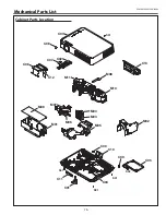
Page 75: ...KR6 XW55A00 KP6 XW50A00 75 Cabinet Parts Location C13 Mechanical Parts List M03 M08 M02 C05 M05 M10 M09 M01 C10 M07 C06 C12 C08 C03 C07 C02 M11 M06 C11 C01 C09 C09 S01 S01 S02 S01 S01 C04 M04 ...

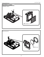
Page 76: ...KR6 XW55A00 KP6 XW50A00 76 Mechanical Parts List S03 S03 L09 Relay out L04 Integrator In Optical Parts Location Integrator Lens In S03 Relay Lens Out ...

Page 77: ...KR6 XW55A00 KP6 XW50A00 77 Mechanical Parts List L13 Polarized in G L14 Polarized in B S03 S03 L03 Projection Polarized Glass In Projection Lens ...

Page 78: ...KR6 XW55A00 KP6 XW50A00 78 Mechanical Parts List L02 Prism LCD panel Ass y L02 3 L02 1 L02 Prism LCD Panel Assy L02 4 Blue Red Green L02 2 ...

Page 79: ...KR6 XW55A00 KP6 XW50A00 79 Mechanical Parts List L11 L01 L12 L15 L06 L16 L10 L07 L05 L07 In the Optical Unit L08 ...

Page 80: ...CREWS S01 411 031 9304 SCR BIN 3X8 S02 412 074 9900 SPECIAL SCREW S03 411 189 6507 BOLT HEX SCT SW W 2 5X5 OPTICAL PARTS L01 645 089 9423 ASSY LENS CONDENSER R L02 610 331 7359 ASSY LCD PNL PSM KR6AC Including Key No L02 1 to L012 4 and LCD Panels L02 1 945 086 6150 POLARIZED GLASS OUT G L02 2 945 086 6167 POLARIZED GLASS OUT B 645 093 1185 POLARIZED GLASS OUT B L02 3 945 088 7988 PREPOLARIZED GLA...

Page 81: ...KR6 XW55A00 KP6 XW50A00 81 Mechanical Parts List ...

Page 82: ... KR6AD Jun 2007 DC 350 Printed in Japan SANYO Electric Co Ltd ...

Page 83: ...service manual original for chassis No KR6 XW55A00 KP6 XW50A00 models PLC XW55A PLC XW50A File with the service manual No SM5110860 00 Note All the information of part numbers and values indicated on these diagrams are at the beginning of production To improve the performance there may be some differences to the actual set When you order the service parts use service parts code mentioned on the pa...

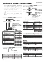
Page 84: ...k Material E Electrolytic P Electrolytic non polarized C Ceramic temperature compensation K Ceramic F Polyester N Polypropylene M Metalized polypropylene H Metalized polypromylar B Ceramic semiconductor G Metalized polyestel Y Composite film S Styrol T Tantalum oxide solid electrolytic U Organic semiconductive electrolyte D Electric double layer electrolytic Mark Tolerance A not specified B 0 1 C ...

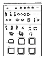
Page 85: ... XW50A00 Pin description of diode transistor and IC OEFY OEFY OEFY 065 OEFY OEFY OEFY OEFY OEFY OEFY 3 4 5 7EE 4 4 BUIPEF OPEF PMMFDUPS BTF NJUUFS SBJO BUF 4 4PVSDF L JPEF L 5SBOTJTUPS 5 L OEFY Diode Transistor FET IC FET ...

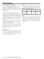
Page 86: ...the components or the circuit board may easily occur Because of this you should use a soldering iron and solder that satisfy the following conditions when carrying out repair work Also soldering work must be done in a short time Soldering iron Use a soldering iron which is 70 W or equivalent and which lets you adjust the tip temperature up to 450 C 842 F It should also have as good temperature rec...

Page 87: ... 1SS352G DDXLBB053G D611H1 K6D_2A 25KK4 7BB C62R 35TM2 2DG C631 1 2GF 150K R618 1 10 GJ 10KC R62B R61B 1SJ68KLBYBV 1 2 25KZ 0 1GQF C605 KZ0 22FA C643 AJ Q622 KK330GQ C658 KK330LBYAG CRF03P D636 1 10 GJ 47KC R62P 1 10GJ 4 7C R62I 1 2 T651H6 1 10GJ 1 5KC R62A K6C_1B C615H2 KK470GQ C62B KK470LBYAG C639_1 D611H2 AH Q602 10KK 0 33GQ C62C 1SS 355 D617 1SS352G DDXLBB053G 450GK 1BS C613 1 10GJ 4 7KC R660 ...

Page 88: ... 3GJ75 R1021 1 16GJ2 2KA R5289 1 16GJ47KA R1031 1 16GJ47KA R2042 1 16GJ10A R4011 1 16GJ100A R5303 X R2031 1 16GJ10A R1043 1 16GJ100KA R2041 1 16GJ 56KA R4013 1 16GZ0A R5308 1 16GJ100A R3062 1 3GJ75 R2032 X R5309 1 16GJ47KA R5202 R3056 1 16GJ1MA 1 16GJ100A R1002 1 16GJ100A R2043 1 16GJ47KA R1091 1 16GJ1KA R1084 X R5304 1 16GJ100KA R3011 1 16GJ10KA R5313 1 16GJ1 5KA R1060 1 16GJ10A R4021 1 16GJ1KA R...

Page 89: ...50 G4 351 F4 190 E2 352 E4 191 D2 353 E5 192 C2 354 E6 193 C3 355 E7 194 C4 356 E8 195 C5 357 E9 196 C6 358 E10 197 C7 359 E11 198 C8 199 C9 360 E12 361 E13 362 E14 363 E15 364 E16 365 E17 366 E18 367 E19 368 E20 369 E21 370 E22 371 F22 372 G22 373 H22 374 J22 375 K22 376 L22 377 M22 378 N22 379 P22 380 R22 381 T22 382 U22 383 V22 384 W22 385 Y22 386 AA22 387 AB22 388 AB21 389 AB20 390 AB19 391 AB...

Page 90: ... 17 A17 18 A18 19 A19 20 A20 21 B20 22 C20 23 D20 24 E20 25 F20 26 G20 27 H20 28 J20 29 K20 30 L20 31 M20 32 N20 33 P20 34 R20 35 T20 36 U20 37 V20 38 W20 39 Y20 40 Y19 41 Y18 42 Y17 43 Y16 44 Y15 45 Y14 46 Y13 47 Y12 48 Y11 49 Y10 50 Y9 51 Y8 52 Y7 53 Y6 54 Y5 55 Y4 56 Y3 57 Y2 58 Y1 59 W1 60 V1 61 U1 62 T1 63 R1 64 P1 65 N1 66 M1 67 L1 68 K1 69 J1 70 H1 71 G1 72 F1 73 E1 74 D1 75 C1 76 B1 77 B2 ...

Page 91: ...5 6 1 SHUTDOWN 2 BYPASS 3 IN 4 IN 5 VO1 6 VDD 7 GND 8 VO2 K8R_0 K8D_0 K6S_0 K6L_3 S3 3VD_PW CJ47CM C2892 LAMP_DET Q7811 RN1117P Q7801 RN1117P GND 1 16GJ51A R7866 1 16GJ100KA R7869 1 16GJ470A R5031 1 16GJ10A R8822 1 16GJ1KA R3581 1 16GF2 2KA R7824 1 16GJ2KA R7874 1 16GJ1KA R5037 1 16GJ10KA R3622 1 16GJ22A R2891 1 16GJ1KA R5063 1 16GF27KA R7871 1 16GJ 10KA R6803 1 16GJ1 2KA R5071 1 16GJ 3 3KA R6809 ...

Page 92: ...A8 SCH_KR6AD 1 3 4 5 6 7 8 9 10 11 1 13 14 15 16 A B C D E F G H I J K L A B C D E F G H I J K L NO DATA ...

Page 93: ... R656 R657 R658 R659 R660 C631 C62A C62B C633 C62C C62D C62E C636 C62F C637 C638 C62I C62J C62K C62M C640 C641 C62R C643 C62T FB694 C654 C655 C656 C657 C658 C660 PTH612 D612 D616 D617 D618 D619 D631 D633 D62R D653 IC651 Q601 Q602 Q621 Q622 Q642 Q651 1 8 9 16 IC621 R653 R62Q R641 C644 D654 Q652 C695 R651 R652 R62Z D636 T651H11 T651H6 T651H1 C615H1 DB611H4 T651H5 C615H2 DB611H1 DB611AH1 D611H2 DB611...

Page 94: ...SIDE 1st Reflow D D C K10A K10B K30B K40A K30A K20A R3801 D3612 R402 R3802 R403 R3803 R3804 1 8 9 16 IC3801 R8821 R8822 R801 C4011 C4012 C4013 SC1001 Q4011 R809 R1307 R1308 C1331 C1332 8 5 1 4 IC1302 R428 20 41 60 61 21 40 1 80 IC561 R429 C4021 C4022 C4023 SC1011 Q4021 L1002 R1512 C401 SC1021 L5661 L5662 L1012 C402 C403 C404 R4011 C406 R4012 C407 R4013 C408 R4014 C409 R4016 C1353 R4017 R4018 C1357...

Reviews: