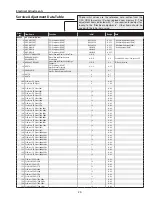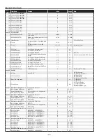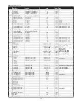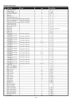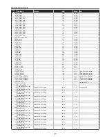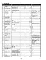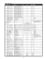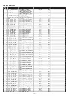
-7-
Electrical Adjustments
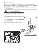
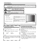
1. Receive the 1 line black/white pattern computer signal
with
computer1 [rGB]
mode.
. Enter the service mode.
3. Project only green light component to the screen.
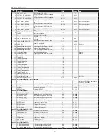
4. Select group no. “
100
”, item no. “
127
” and change data
value to obtain the minimum flicker on the screen.
5. Project only red light component to the screen.
6. Select item no. “
128
” and change data value to obtain
the minimum flicker on the screen.
7. Project only blue light component to the screen.
8. Select item no. “
129
and change data value to obtain
the minimum flicker on the screen.
m
Common Center adjustment
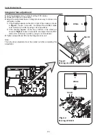
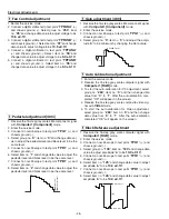
1. Receive the 16-step gray scale computer signal with
computer1 [rGB]
mode.
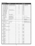
. Enter the service mode, select group no. “
100
” item
no. “
7
” (Red) or “
8
” (Blue), and change Data values
respectively to make a proper white balance.
Confirm that the same white balance is obtained in video
and computer input.
.
White Balance adjustment [PC]
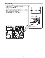
1. Receive the 16-step grey scale computer signal with
computer1 [rGB]
mode.
. Enter the service mode.
3. Connect an oscilloscope to test point “
tPG1
” (+) and
chassis ground (-).
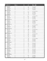
4. Select group no. “
100
”, item no. “
6
” and change data
value to adjust amplitude “
a
” to be
1.6 ±0.1V
.
(a)
white level
white level
,
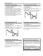
50% White adjustment [PC]
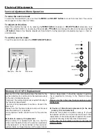
1. Receive the 16-step grey scale composite video sig-
nal with
Video
mode.
. Enter the service mode.
3. Connect an oscilloscope to test point “
tPG1
” (+) and
chassis ground (-).
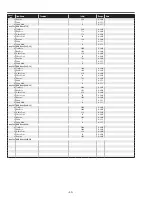
4. Select group no. “
100
”, item no. “
6
” and change data
value to adjust amplitude “
a
” to be
2.2 ±0.1V
.
(a)
white level
white level
⁄0
50% White adjustment [Video]
1. Receive the 16-step grey scale composite video sig-
nal with
Video
mode.
. Enter the service mode, select group no. “
100
” item
no. “
7
” (Red) or “
8
” (Blue), and change Data values
respectively to make a proper white balance.
Confirm that the same white balance is obtained in video
and computer input.
⁄1
White Balance adjustment [Video]
Note On White Uniformity Adjustment
If you find the color shading on the screen, please ad-
just the white uniformity by using the proper computer
and “Color Shading Correction” software supplied sep-
arately.
The software can be ordered as follows;
coLor SHAdING correctIoN Ver. 4.00
Service Parts No.
645 075 9611
Summary of Contents for 1 122 356 20
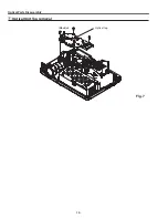
Page 18: ... 18 Optical Parts Disassembly m Optical Unit Top removal M3x8 x5 Optical top Fig 7 ...
Page 53: ... 53 IC Block Diagrams FA5502 P F Control IC621 L3E6100D D A S H LCD Driver IC501 IC531 IC561 ...
Page 54: ... 54 IC Block Diagrams L3E07072 LCD Driver Gamma Correction IC401 M62393 DAC IC3531 ...
Page 55: ... 55 IC Block Diagrams NJW1141 Audio Control IC5001 ...
Page 81: ...KR6 XW55A00 KP6 XW50A00 81 Mechanical Parts List ...
Page 82: ... KR6AD Jun 2007 DC 350 Printed in Japan SANYO Electric Co Ltd ...


