Sanwa M11X Operating Manual Download Page 12

Page 12

LCD Menu keys

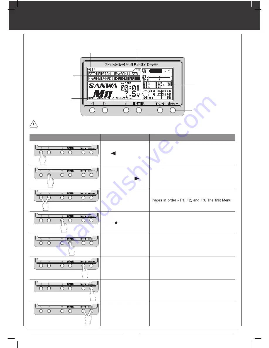
The SANWA M11X FHSS-3 2.4GHz transmitter features six menu keys for menu operation. This section summarizes the functions 

of each of the 6 menu keys in addition to describing the main areas of the LCD Display.

Model Number

Menu Function

Programming

Window

Help Display

Area

Key Pad

Information 

Window

Function Page

Moves the Menu Function cursor left (backward) 

to  the  previous  menu  function.  Turning  the  Dial 

Knob  counter-clockwise  will  move  the  Menu 

Function cursor left, too.

Moves the Menu Function cursor right (forward) 

to the next menu function. Turning the Dial Knob 

clockwise  will  move  the  Menu  Function  cursor 

right, too.

Function Page Select

Key Sequence

Pressing both keys will scroll through the Function 

Function will be highlighted on each page.

KEY

NAME

FUNCTION

Moves  the  Cursor  backward  in  the  Programming 

Window. Also used in the Help Display Area and 

to display the Information Window.

Enter Key

Moves  the  Cursor  forward  in  the  Programming 

Window. Also used in the Help Display Area.

INC/+ Key (Increase)

Increases  number  values  in  the  Programming 

Window. Also scrolls up a Selection List.

DEC/- Key (Decrease)

Decreases  number  values  in  the  Programming 

Window. Also scrolls down a Selection List.

INC/+ and DEC/-

Key Sequence (Reset)

Pressing both keys together will Reset the selection 

to the Factory Default Setting.

A plastic cover is included that snaps over the LCD display and key pad to protect it during travel or storage.

Scroll Key

Function Key

Function Key

Summary of Contents for M11X

Page 1: ...OPERATING MANUAL 670A12978A ...

Page 2: ...ion 3 Usage Precautions 4 5 Features Familiarization Features and Specifications 6 8 Driving Position Adjustments 9 10 Charging the Battery 11 LCD Menu Keys 12 Transmitter and Receiver Binding 13 Function Pages 14 Menu Flow Chart 15 Battery and Operating Timer 16 Steering Dual Rate 17 End Point Adjustment 18 20 Exponential 21 22 Adjustable Rate Control 23 24 Servo Speed 25 26 Anti Lock Braking 27 ...

Page 3: ...self for others and for your equipment operate your radio control equipment If at any time during the operation of your model should you feel or observe erratic operation or abnormality end your operation as quickly and safely as possible DO NOT operate your model again until you are certain the problem has been corrected TAKE NO CHANCES Your model can cause serious damage or injury so please use ...

Page 4: ...ty for damages resulting from use of components other than genuine SANWA components Turn the receiver ON After using your model turn transmitter OFF It can be dangerous if you activate the components in reverse order as the servos may start up inadvertently Before use double check that the Never touch the transmitter antenna during use Doing so may cause loss of transmitter output making it imposs...

Page 5: ...GHz FHSS 3 Receiver Model RX 451 Frequency 2 4GHz FHSS 3 Input Voltage 4 8v 6 0v Weight 9g Dimensions 36 5 x 24 0 x 15 0mm Fail Safe Limit 3 8v Default 3 5v 5 0v Adjustable Torque 5 9kg cm 4 8v 7 4kg cm 6 0v Speed 0 13 sec 60º 4 8v 0 10 sec 60º 6 0v Dimensions 39 1 x 20 1 x 37 3mm Weight 56g Torque 11 2kg cm 4 8v 14 0kg cm 6 0v Speed 0 15 sec 60º 4 8v 0 12 sec 60º 6 0v Dimensions 39 1 x 20 1 x 37 ...

Page 6: ...chor Charging Jack Power Switch Battery Compartment Push Button Switch Sw 2 Push Button Switch Sw 2 Push Button Switch Sw3 Trim Control Switch Trm 4 Trim Control Switch Trm 5 Trigger LCD Display LEFT Use the diagrams below and on the next page to familiarize yourself with the different system controls on your new M11X FHSS 3 2 4GHz transmitter and RX 451 receiver Descriptions of these features can...

Page 7: ...DSC Trim Control Switch Trm 4 Battery Compartment Push Button RIGHT Grip Bind Key Bind LED Coaxial Cable Antenna Reception Wire Batt DSC Aux 2 CH 4 Aux 1 CH 3 Throttle CH 2 Steering CH 1 Negative Black Positive Red S Signal Blue Trim Control Switch Trm 5 BACK ...

Page 8: ...without actually turning the transmitter ON This allows you to check and or change programming settings without actually turning ON the transmitter To turn the LCD Display ON using the Display Switch push and hold the Display Switch forward for 1 second To turn the LCD Display OFF push the Display Switch forward quickly Grip Features a molded rubber pad for increased control and feel The driving p...

Page 9: ...amaging the wires that are connected on both units 3 Adjust the throttle trigger spring tension using a 1 5 mm hex wrench To increase throttle trigger spring tension tighten the hex screw turn clockwise To decrease throttle trigger spring tension loosen the hex screw turn counter clockwise 4 After resetting the throttle trigger spring tension align the upper transmitter unit and reinstall it using...

Page 10: ...t Right selector switch to L located above the Trm 4 and Trm 5 switches 4 Rotate the grip by 180 degrees then align the upper transmitter unit and reinstall it using the two M4 socket head cap screws STEERING WHEEL POSITION 1 1 4 Rotate the digital trim ring to the desired position The positions Set the digital trim ring at the desired position then retighten the three M2 6 socket head cap screws ...

Page 11: ...he charger included with the transmitter to charge a Li Po battery You MUST use a dedicated Li Po battery charger When you change the connector on your Li Po battery please observe correct polarity CHARGING THE TRANSMITTER BATTERY An after market peak detection charger can be used to charge the NiMH transmitter battery however the battery must circuitry within the transmitter will interfere with t...

Page 12: ...t too Function Page Select Key Sequence Pressing both keys will scroll through the Function Function will be highlighted on each page KEY NAME FUNCTION Moves the Cursor backward in the Programming Window Also used in the Help Display Area and to display the Information Window Enter Key Moves the Cursor forward in the Programming Window Also used in the Help Display Area INC Key Increase Increases ...

Page 13: ...SEND BIND COMMAND will be displayed in the Programming Window When the binding procedure is successful the Bind LED on the receiver will stay solid blue when both the transmitter and receiver are turned ON If the Bind LED on the receiver is blinking rapidly the transmitter and receiver are not paired In this case turn both the transmitter and receiver OFF then repeat the binding procedure The M11X...

Page 14: ...ing individual functions l Steering Dual Rate l End Point Adjustment l Exponential l Adjustable Rate Control l Steering Brake Servo Speed l Anti Lock Braking l Traction Control l Model Naming Model Select Model Copy Function Menu F2 consists of the following individual functions l Servo Sub Trim l Track Timers l Servo Reversing l Start Position l Throttle Hold l Brake Mixing l Compensation Mixing ...

Page 15: ... MIX2 f2 function page 2 SUB T TH SUB T 3CH SUB T 4CH SUB T ST REV TH REV 3CH REV 4CH BR MIX SIGNAL USER C MENU BATT f3 function page 3 SET UP SYSTEM SET UP MOD SET UP BIND ASGN SW ASGN TRIM F SAFE FAIL SAFE VR ADJ F SAFE B FAIL SAFE The following Menus are the result of pushing the Right Function key FUNCTION PAGES SPECIAL NOTES EPA 3CH Channel 3 or Auxiliary Channel 1 EPA 4CH Channel 4 or Auxili...

Page 16: ...ation and recharge the transmitter batteries Continuing to use the transmitter after the low voltage alarm sounds can result in loss of control of your model Will start blinking if battery voltage reaches 6 7 volts TRANSMITTER BATTERY VOLTAGE OPERATING TIMER The Operating Timer is a count up timer that records the time the transmitter has been turned on in hours and minutes This timer can be reset...

Page 17: ...ual Rate amount At this time set the dual rate to 125 This will increase the servo movement by 25 in both left and right directions 5 After the Dual Rate has been set adjust the independent left and right End Points using the EPA feature See the next page for information on setting the EPA 1 Set the digital steering trim to 0 using the Trm 1 switch You can see when the trim reaches 0 by viewing ei...

Page 18: ...at full travel TH throttle end point adjustment Your model s carburetor may not open completely or opens too much and causes the servo to bind If you re using an ESC the ESC may not command full power or the brake may not engage adequately In such cases the throttle high and low points and the brake is adjustable 1 Press the Function key to move the cursor to TH in the EPA Programming Window 2 To ...

Page 19: ...KE channel the End Point Adjustment can be set separately from the Auxiliary Channel 4 BRAKE activated using the throttle trigger brake function 1 Make sure that 4CH Mode is selected in the SET UP menu and 0 4 s e g a p e e S u n e m X I M R B e h t n i T C A o t t e s s i E K A R B H C 3 t a h t and 47 for more information 2 Press the Function key to move the cursor to 3CH in the EPA Programming ...

Page 20: ...graph shows only the TH 4CH balance THIS SPACE INTENTIONALLY LEFT BLANK Auxiliary Channel 4 is used exclusively for braking purposes When using Auxiliary Channel 4 as the additional BRAKE channel End Point Adjustment can be separately set from Auxiliary Channel 3 BRAKE 1 Make sure that 4CH is selected in the SET UP menu and that 4CH BRAKE is set to ACT in the BR MIX menu See pages 40 and 47 for mo...

Page 21: ...rs reduce the Exponential value and if your model under steers increase the Exponential value EXP ST setting range is between 100 Mild to 100 Quick The default setting is 0 Linear TWEAK Setting Use the TWEAK setting when you want to fine tune the left and right steering balance This allows you to move and pinpoint the neutral position of the Exponential function independently anywhere between the ...

Page 22: ...function it must be Activated Press the ENTER key to move the cursor to EXP then press the INC or DEC keys to either ACT Activate or INH Inhibit the Exponential function The EXP TH ACT INH setting can be assigned to any Push Button switch using the Key Assign function See page 50 for more information By using this function switching Exponential ON or OFF can be selected during model operation The ...

Page 23: ...to Quick In general if your model over steers reduce the Adjustable Rate Control value and if your model under steers increase the Adjustable Rate Control value RATE Setting 1 Press the Function key to highlight the ARC menu ST will be active in the Programming Window and the cursor will default below RATE 2 Press the INC or DEC keys to set the desired RATE value ARC ST RATE setting range is betwe...

Page 24: ... throttle trigger forward The cursor will point to the right Press the INC or DEC keys to set the desired POINT value ARC TH POINT setting range is between 5 to 95 The default setting is 50 ACT INH Setting 1 To use the Steering Adjustable Rate Control function it must be Activated Press the ENTER key to move the cursor to ARC then press the INC or DEC keys to either ACT Activate or INH Inhibit the...

Page 25: ...nge is 0 to 100 The default setting is 0 The FORWARD setting adjusts the SPEED of the servo from Neutral to the Right or the Left RETURN Setting 1 Press the ENTER key to move the cursor to RETURN then press the INC or DEC keys to set the desired RETURN value SPEED ST RETURN setting range is 0 to 100 The default setting is 0 The RETURN setting adjusts the SPEED of the servo back to Neutral POINT Se...

Page 26: ... the INC or DEC keys SPEED BR RETURN setting range is 0 to 100 The default setting is 0 The RETURN setting adjusts the SPEED of the servo back to Neutral POINT Setting 1 Press the ENTER key to move the cursor to POINT then press the INC or DEC keys to set the desired POINT value SPEED BR POINT setting range is 5 to 100 The default setting is 100 The POINT setting locates the actual point in the se...

Page 27: ...s the amount of delay before the ALB activates after reaching the POINT SPEED Setting 1 Press the ENTER key to move the cursor to SPEED then press the INC or DEC keys to set the desired SPEED value ALB SPEED setting range is 1 to 30 The default setting is 2 The SPEED setting controls how quickly the Brake pulsates Set the hardest braking you can obtain from your model by carefully setting Anti Loc...

Page 28: ...reducing the chance of tire spin even when the throttle trigger is applied abruptly Traction Control also contributes to stability during acceleration providing smoother running Ideal smoothness can be further refined by adjusting for intermittent locking in addition to normal servo speed delay adjustment By making point settings and switch assignments with the key assign function Traction Control...

Page 29: ... control Forward Traction Control changes the Traction Control settings when the throttle is moving from Neutral to the High position There is no traction control setting for the Brake side POINT 5 to 100 Neutral High TRACTION Setting 1 Press the Function key to highlight the TR CTL menu FWD will be active in the Programming Window and the cursor will default to TRACTION 2 Press the INC or DEC key...

Page 30: ... function it must be Activated Press the ENTER key to move the cursor to TR CTL then press the INC or DEC keys to either ACT Activate or INH Inhibit the TR CTL RTN function The TR CTL RTN ACT INH setting can be assigned to any Push Button switch using the Key Assign function See page 50 for more information By using this function switching Traction Control ON or OFF can be selected during model op...

Page 31: ...icular model within the MODEL SELECT screen 1 Press the Function key to move the cursor to NAME in the MODEL Programming Window The cursor will blink next to the M01 selection 2 The cursor will blink next to the M01 selection Press the ENTER key to move the cursor to the right and press the key to move the cursor to the left 3 Press the INC or DEC keys to select a character then press the ENTER ke...

Page 32: ...gramming Window 2 To copy data from another model SLAVE to the currently selected model MASTER press the key to change the currently selected model to Slave The cursor will point to the left and MASTER will be displayed above the model you would like to copy from Clearing Model Data 1 Press the Function key to move the cursor to COPY CLEAR in the MODEL Programming Window 2 Press the key to change ...

Page 33: ...e steering and throttle servo horns remain centered When adjusting linkages Sub Trim allows you to fix an accurate center position It s not unusual thet when you center a servo and install the servo horn the servo horn is not perfectly centered Sub trim allows you to center the servo horn perfectly without altering the servo End Point travel Steering Trim Throttle Trim Brake Trim Steering Trim Thr...

Page 34: ...ning On the Lap Timer Count Up Timer 1 Press the Function key to highlight the TIMER menu LAP will be active in the Programming Window and the cursor will default to OFF 2 Press INC or DEC keys to turn the Lap Timer ON TIMER LAP GOAL setting range is 10 seconds to 60 minutes in 10 second increments The default setting is 60 minutes The Pre Alarm sounds the programmed number of seconds prior to the...

Page 35: ...Interval Timer for minutes and seconds and one Interval Timer for seconds and milliseconds Both Interval Timers can be used simultaneously and different Tones can be assigned to each The Lap Timer Switch can be assigned to another Push Button switch using the Key Assign function See page 50 for more information Sw 3 The Cumulative Time cannot be manually cleared It will be automatically cleared wh...

Page 36: ...ond increments and 0 milliseconds to 90 milliseconds in 10 millisecond increments The default setting is 00 seconds and 00 milliseconds Starting the Interval Timer s 1 In the default configuration the Interval Timer Switch is assigned to Sw 3 To start the Interval Timer press the Interval Timer Switch Both Interval Timers will start counting up When Interval Timer T2 reaches the preset time an ala...

Page 37: ... in 1 minute increments 0 seconds to 59 seconds in 1 second increments and 0 milliseconds to 90 milliseconds in 10 millisecond intervals The default setting is 00 minutes 00 seconds and 00 milliseconds Starting the Countdown Timer 1 In the default configuration the Countdown Timer Switch is assigned to Sw 3 To start the Countdown Timer press the Countdown Timer Switch The Countdown Timer will star...

Page 38: ... value S POS S POS setting range is 100 to 100 The default setting is 0 The S POS setting controls how far the throttle servo will hold open the carburetor when SPO is activated Alarm Setting 1 Press the ENTER key to move the cursor to ALARM in the Programming Window then press INC or DEC keys to set the ALARM ON or OFF S POS ALARM setting range is ON or OFF The default setting is ON The ALARM wil...

Page 39: ...ed Throttle Hold will be active again The THROTTLE HOLD function must be assigned to a Push Button switch using the Key Assign function See page 50 for more information We suggest assigning it to its own switch for example Sw 2 Throttle Hold Setting 1 Press the Function key to highlight the TH HLD menu The cursor will default below THROTTLE HOLD in the Programming Window 2 Press INC or DEC keys to...

Page 40: ...ing is 0 The 2CH DELAY setting controls the speed of the Brake Side of the throttle servo When the value is increased the speed of the Brake Side of the throttle servo is slowed while the speed of the 4th channel brake servo remains normal This results in the 4th channel brake servo reaching its End Point before the Brake Side of the throttle servo reaches its End point 4CH Delay Setting 1 Press t...

Page 41: ...ttle servo will not function but the 4th channel brake servo and the 3rd channel brake servo if set to ACT will continue to function When set to INH both the Brake Side of the throttle servo and any separate Brake servos will function normally BR MIX TH BRAKE CUT should ONLY be set to ACT if you are using one or two separate brake servos If you set TH BRAKE CUT to ACT while only using the 2nd chan...

Page 42: ... AUX2 Master 1 Compensation Mixing outputs the raw operation data Master 2 Compensation Mixing outputs the raw operation data plus the calculated operation of certain programming options as described in the table at the bottom of the page 100 100 Steering Wheel Steering Operation Throttle Operation Calculation Calculation Servo Output Servo Output CH2 CH1 Master 1 Master 2 100 100 10 10 Steering S...

Page 43: ...nnel can be mixed at any one time Slave Setting 1 Press the ENTER key to move the cursor to SLAVE then press the INC or DEC keys to choose which channel you want to be the SLAVE Choose from either ST TH AUX or BR Offset Setting The OFFSET setting is primarily used to center the SLAVE servo and set the neutral position for the origin for Mixing when the Master 2 servo has Sub Trim programmed Second...

Page 44: ...et to 100 ACT INH Setting 1 To use the C MIX1 function it must be Activated Press the ENTER key to move the cursor to C MIX then press the INC or DEC keys to either ACT Activate or INH Inhibit the C MIX1 function The C MIX1 ACT INH setting can be assigned to any Push Button switch using the Key Assign function See page 50 for more information By using this function switching C MIX1 ON or OFF can b...

Page 45: ...n screen in the Information Window This allows you to view the Servo Monitor function while making setting adjustments in many of the Programming Menus Servo Monitor Programming Window Information Window The Servo Monitor function screen can be displayed in the Information Window while in the following Programming Menus Function Page 1 EXP ARC SPEED ALB TR CTL Function Page 2 SUB T TIMER REV S POS...

Page 46: ... default setting is INH When set to ACT the transmitter will vibrate at the same time that the Timer alarms or the battery alarm activates When set to INH the transmitter will not vibrate ON Power Logo Setting 1 Press the ENTER key to move the cursor to OP LOGO then press the INC or DEC keys to select ACT or INH SET UP SYSTEM OP LOGO setting range is ACT and INH The default setting is ACT When set...

Page 47: ...ery will be drained Transmitter set up MOD MODULATION AND CHANNEL MODE SET UP The Modulation Set up function allows you to choose the transmitter Modulation Type and Channel Mode 2CH or 4CH and Analog and or Digital servo selection Modulation Type Setting 1 Press the Function key to move the cursor to MOD in the Programming Window The cursor will default to TYPE 2 Press the INC or DEC keys to set ...

Page 48: ...half and the second half of a tone making it easier to differentiate between the two halves Tones can be selected from among 10 different tones providing a total of 100 pattern combinations for the first half and last half of signals Function Page 3 SIGNL Command Tone Setting 1 Press the Function key to highlight the SIGNL menu The cursor will default to COMMAND in the Programming Window next to t...

Page 49: ...l settings the selected Tone is sounded The INT T1 Tone setting affects the Minutes portion of the Interval Timer Interval Timer Seconds Tone Setting 1 Press the ENTER key to move the cursor to the left side INT T2 S08 setting then press the INC or DEC keys to adjust the desired Tonal value for the first half S08 setting 2 Press the ENTER key to move the cursor to the right side INT T2 S08 setting...

Page 50: ... 5 Push Button Switch Sw 3 The following Switch and Trim Functions are the factory default settings Trm 1 Steering Trim Trm 2 Throttle Trim Trm 3 4th Channel Brake Trim Trm 4 Dual Rate Trm 5 Brake End Point Adjustment Sw 1 Starting Position ON OFF Sw 2 Anti Lock Brake ON OFF Sw 3 Timer ON OFF SW SWITCH KEY ASSIGN The Switch Key Assign function allows you to assign the ON OFF control of various fun...

Page 51: ...R LAP INT DWN SPO BRL HLD CX1 CX2 Sw 2 Sw 3 Sw 3 Sw 3 Sw 1 TRIM TRIM KEY ASSIGN to the Dial Knob This allows you to choose the Trim function positions that are best suited to your situation Trim Resolution Trim or Reverse direction too Trim Switch Function Display Current trim assignments and trim values are shown in the Trim Switch Function Display Screen in the Information Window When more than ...

Page 52: ...m resolution key assignments Trim Direction Setting 1 Press the ENTER key to move the cursor to REV then press the INC or DEC keys to set the desired trim direction value ASGN TRIM REV setting range is NOR and REV The default setting is NOR When set to NOR the trim switch will move the servo the same direction as the steering wheel When set to REV the trim switch will move the servo the opposite d...

Page 53: ...3CH Brake Mixing Delay 4CH Compensation Mixing 1 Offset Compensation Mixing 1 High Compensation Mixing 1 Low Compensation Mixing 2 Offset Compensation Mixing 2 High Compensation Mixing 2 Low Trim Steering Trim Throttle Trim Brake Auxiliary Channel 3 Function Keys SP S F SP S R SP S P SP B F SP B R SP B P ALB PT ALB ST ALB LG ALB SP TR T F TR T R TR D F TR D R TR P F TR P R S POS TH HLD BM 2CH BM 3...

Page 54: ...g several characters from the same group 2 Press the INC or DEC keys to select a character then press the ENTER key to advance the cursor to the next space Repeat to enter the rest of the characters A group of character styles can be selected by pressing the INC and DEC keys at the same time Choose from capital letters lower case letters symbols higher case numerals and lower case numerals To eras...

Page 55: ...nal is lost 3 With the cursor next to TH FS 0 move the throttle trigger toward the Brake Side the amount you want the brake to engage when Fail Safe Activates 4 Press the INC and DEC keys at the same time to set the Brake Side Fail Safe setting as noted by the Point on the graph and the percentage value 5 Repeat the previous procedures to set the Fail Safe settings for the desired remaining channe...

Page 56: ...ts however the minimum operating voltage of most servos is higher than that B F S Setting 1 Press the Function key to move cursor to B FAIL SAFE in the Programming Window The cursor will default to B F S 2 Press the INC or DEC keys to set the desired value RX V Setting 1 Press the ENTER key to move cursor to RX V then press the INC or DEC keys to adjust the desired receiver voltage value RX V sett...

Page 57: ... the Programming Window 6 Press the INC key to Execute the VR ADJUSTMENT process EXECUTING will be displayed in the Programming Window To Cancel the VR Adjustment process press the DEC key For the VR ADJUSTMENT Process to EXECUTE without an ERROR message you MUST complete both steps 3 and 4 If you only complete step 3 or step 4 the VR ADJUSTMENT process will not EXECUTE The numbers displayed at th...

Page 58: ...he currently programmed VR ADJUSTMENT setting OVER will be displayed In this case you should repeat steps 2 6 on the previous page to reset the VR ADJUSTMENT 3 Press the Function key to highlight the VR ADJ menu 4 After adjusting the grub screws verify that the Calibration number in the center of the bar graph is the same when the steering wheel is turned in both directions For example if you turn...

Page 59: ...ramming Window The selected Menu will display in the upper left box in the C1 Custom Function Page 3 Press the ENTER key to move the cursor to the next box in the C1 Custom Function Page then press the INC or DEC keys to scroll through the different Menu selections to display the selected Menu 4 Repeat step 3 to add your most accessed menus into the remaining boxes in the C1 Custom Function Page P...

Page 60: ...is ON Command signals are disabled Key lock switch is ON A negative value is set in the servo Speed menu Low battery Linkage stiff or binding Trim or Sub Trim not centered D RATE and EPA settings are too large Trim is outside of operational range Timers are set in the OFF position Spring tension set too loose Too much time elapsed after pressing receiver Bind button AttemptingtoBindanincompatible ...

Page 61: ...ble can be bent into gentle curves however do not bend the Coaxial Cable acutely or repeatedly bend it or the antenna core can be damaged The Coaxial Cable should be installed through a nylon tube antenna tube in the vertical position for the best reception Compensation Mixing Allows you to mix two channels together then apply that mixing to the channels themselves For example you can use Compensa...

Page 62: ... Also scrolls up a Selection List Inhibit To deactivate or turn OFF a particular function Information Window An area on the right side of the LCD Display that displays a number of different informational items that relate to the current settings of the transmitter and its various functions The Servo Monitor can also be displayed in this area by pressing the Scroll key Interval Timer target time Th...

Page 63: ...can be adjusted to best suit your driving style Step Value A preset amount that the servo will travel when the trim switch is pressed once The step value can be adjusted so that the servo either moves more or moves less when the trim switch is pressed Sub Trim Corrects the neutral trim setting for steering and throttle making it possible to center the trim switches while ensuring the steering and ...

Page 64: ...ng 5 14 15 40 41 53 61 Brake Point Setting 38 Brake Side Setting 22 C Charging 6 8 11 61 Charging Jack 6 8 61 Coaxial Cable 7 8 61 Compensation Mixing 14 42 51 53 61 Countdown Timer 36 37 49 51 61 Custom Menu 14 59 61 D DEC Key 12 61 DELAY Setting 29 30 Dial Knob 5 6 8 12 19 44 50 51 52 53 61 Digital Trim 5 Direct Servo Control Jack 8 61 Display Switch 5 6 8 45 61 63 Dual Rate Steering 5 E End Poi...

Page 65: ...ck Switch 5 6 8 62 L Lag Setting 62 Lap Timer 34 35 49 51 62 LCD Display 5 6 8 12 14 46 47 61 62 63 Li Po Battery Use 11 M Menu Flow Chart 15 Model Copy 5 14 31 Model Naming 5 14 Model Select 5 14 31 O Offset Setting 38 43 Operating Voltage 5 62 Output Power 5 62 P Parallel Trim 33 62 Point Setting 38 62 Power Indicator Light 8 Power Switch 6 8 62 Programming Window 12 63 Push Button Switch 8 63 R...

Page 66: ... 50 51 53 63 Starting Position Setting 38 Steering Dual Rate 14 17 18 63 Steering Wheel 5 6 8 9 10 42 45 58 63 Steering Wheel Tension 5 9 Step Value 63 STROKE Setting 27 Sub Trim 5 14 18 33 40 42 43 45 60 63 T Throttle Hold 5 14 39 51 53 63 Traction Control 5 14 28 29 30 51 53 63 TRACTION Setting 29 30 Trigger 6 8 9 28 45 63 Trim Control Switch 8 63 Tweak 5 62 U User Naming 5 V Variable Rate Adjus...

Page 67: ...Page 67 notes ...

Reviews: