57
1.
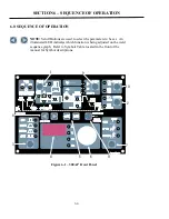
Pulse Function
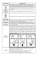
– Pressing this button enables the TIG current pulse functions.
2.
Remote Current Function
– Pressing this buttons enables remote current functions.
3.
TIG Mode Functions
– Pressing this button scrolls through the output TIG function modes.
The user can select between Standard, Slope, Slope w/repeat or Spot modes.
4.
Digital LED Display
– Welding amperage and parameter values are displayed in this window.
Internal error codes such as over temperature, low or high input voltage applied and others are
signaled to the operator by means of a warning sound and indicated on the Digital LED display.
5.
Save/Load Buttons
– Used to easily Save and Load (retrieve) up to 5 welding parameter
sequences.
6.
Control Knob
– Rotating this knob will adjust the value of the function selected. This knob
allows the operator to adjust the output amperage within the entire range of the power source as
well as adjusting the value of each function. Pushing the knob inward displays actual welding
voltage.
7.
Process Button
– Pressing this button selects between STICK, Lift TIG or HF TIG welding
processes.
8.
Scroll Buttons
– Used to scroll through the available welding functions to be set as shown on
the on the welding sequence graph. The LEDs in the graphical representation will illuminate
indicating which function has been selected and available for adjustment. Once the desired
function has been selected, use the Encoder Knob to adjust the function’s value.
GAS CHECK
– Press and hold the Back button to enter gas check mode.
During gas check,
“GAS” is displayed on the LED Display and welding is not possible. To end gas check, press
and hold the back button during gas check, or gas scheck will end automatically after 2 minutes.
9.
AC/DC Button
– Selects between DC or AC or AC-SOFT welding output.
10.
Contactor Function
– Pressing this buttons enables Contactor Functions.
11.
Water Cooling
– Pressing this button enables the WATER COOLOING pressure sensor
circuitry that is intended for use with water cooled torches. The WATER COOLING pressure
sensor can be enabled in ALL welding processes and may inhibit output current during welding
processes that normally do not utilize water cooling equipment. The WATER COOLING
function should be disabled when no water cooling equipment is utilized.
Summary of Contents for IA-3000TP-U3E
Page 2: ......
Page 4: ......
Page 8: ......
Page 26: ...26 PAGE LEFT INTENTIONALLY BLANK ...
Page 32: ...32 PAGE LEFT INTENTIONALLY BLANK ...
Page 54: ...54 PAGE LEFT INTENTIONALLY BLANK ...
Page 74: ...74 PAGE LEFT INTENTIONALLY BLANK ...
Page 87: ...87 PAGE LEFT INTENTIONALLY BLANK ...
Page 94: ...PAGE LEFT INTENTIONALLY BLANK ...
Page 97: ...PAGE LEFT INTENTIONALLY BLANK ...

