02-2014
VERONA RS
EN
Instructions for use and maintenance
11 / 29-EN
2
3
1
L2
L1
L2
L1
L2
L3
L2
L3
L1
L1
N
N
120V.
L1
N
L1
N
230V.
400V 3N
4
G
B
B
B
W
BL
BL
Y/G
Y/G
BR
BR
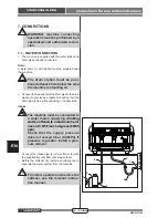
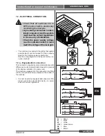
7.2 - ELECTRICAL CONNECTION
• Check that all switches are in
OFF position before electrically
connecting the machine.
• A grounding connection is abso-
lutely compulsory and the system
must meet the current regulations
in the country of installation.
• Check the power supply voltage
(see the indication label); it must
match the voltage of the local grid.
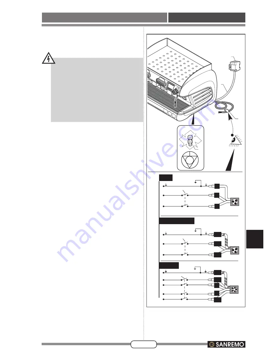
•
The machine is connected to the grid by the supplied
power cable (2) and to a breaker (3) that is properly
sized for the machine power consumption.
See the wiring diagrams in the figure for the con
-
nection method.
7.2.a - Equipotential connection
This connection, required by some standards, prevents
differences in electrical potential between the grounds
of the devices installed in the same room.
The machines prepared for this connection are fitted
with the relevant terminal (4) located on the bottom of
the machine.
•
Connect an external equipotential connector of the
proper size to the relevant terminal (4), in compli-
ance with current regulations.
G
= Green
B
= Black
W
= White
Y/G
= Yellow/Green
BL
= Blue
BR
= Brown

