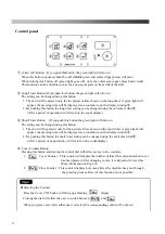
Other Operations
How to Reset Emergency Stop
Pressing the emergency stop button or safety bars will make all operations stop and will return the
machine to the start position.
The display will display
“
E 1
”
(
Emergency button
)
“
E 2
”(
Left safety bar
)
and
“
E 3
”(
Right safety bar
)
.
How to Release
・
If you push the emergency stop button, turn the emergency stop button clockwise to release the lock on
the button. (“— — 1 “will be displayed.)
Push the reset button and the machine will return to its normal condition.
・
If you push safety bar, Push reset button and the machine will return to its normal condition.
*
If you don’t push reset button, the machine will not work.
About a Cover Counter
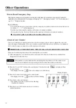
The Cover Counter was created to make it easy for the customer to know when to change the cover and
insure the proper finish quality. If the cover counter exceeds 10,000 times, there will be an error displayed
(EC1) when the power is turned on, and the machine will not start.
※
THEREFORE, AFTER CHANGING THE COVER, ALWAYS RESET THE COUNTER
Please use the following instructions when resetting the cover counter.
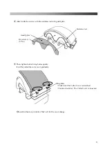
①
After changing the cover, turn the machine on and press the blue reset button for an extended time.
Doing this will cancel the error.
It IS possible to use the machine after completing this step. However, if the counter is not
reset, the reset button must be pressed again the next time the machine is turned on.
②
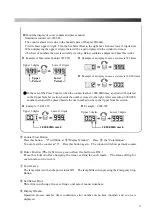
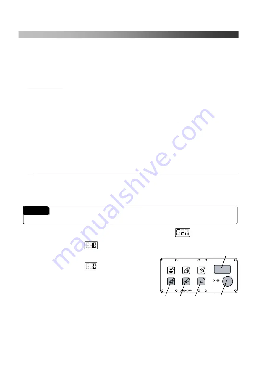
Press the ‘Cover CNT’ button on the control panel. Turn the dial until
is displayed. Press
the enter button.
→
The display will show (This is the display for 10,000 times)
③
Press the Counter Clear button on the control panel.
→
The display will show , and the 0 will start flashing.
④
Press Enter on the control panel.
→
The display will show a solid 0 with no flashing.
The Reset is finished.
⑤
Press the Cover CNT button once more to return to
standard operation.
②
Display Window
③
④
②
⑤
②
Caution
18
Summary of Contents for LP-660E-V2
Page 2: ......
Page 38: ...36...
Page 39: ...Spare Parts List Index 1 Front Diagram 2 Rear Diagram 3 Steam Piping 4 Cover Diagram 37...
Page 40: ...1 Front Diagram REV 1 38...
Page 44: ...3 Steam Piping REV 1 42...
Page 46: ...4 Cover Diagram REV 1 44...
Page 50: ......
Page 51: ......
Page 52: ......
Page 53: ......


