


38
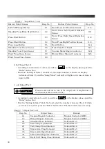
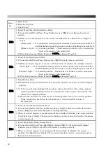
Chart 1
“Input Test 1” List
Button / Pedal / Sensor
Disp. No.
Button / Pedal / Sensor
Disp. No.
Left Cuff Clamp Button
S 1
Front Press Left Position Sensor
S 10
Shoulder Press/Slide Start Button
S 2
Front Press Left Speed Reduction
Sensor
S 11
Press Start Button
S 3
Front Press Right Speed Reduction
Sensor
S 12
Press Short Button
S 4
Front Press Right Position Sensor
S 13
Press Long Button
S 5
Reset Button
b1A
Shoulder Press Close Sensor
S 6
Neck Close Foot Pedal
b1b
Shoulder Press Open Sensor
S 7
Vacuum Motor Magnet contactor
b2A
Front Press Open Sensor
S 8
Blower Motor Magnet Contactor
b2b
Front Press Close Sensor
S 9
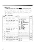
2.
In2
(
Input Test 2
)
・
According to instructions 1 and 2, you will see on the display, please push the
“Enter” button No.4.
・
Dial the “Setting & Select ” knob No.5, the input number is shown on display
(reference Chart 1), and the “Long Timer” button No.3 lights on in case of item of
input is ON.
3.
out
(
Output Test
)
・
According to instructions 1 and 2, you will see on the display, please push the
“Enter” button No.4.
・
Dial the “Setting & Select” knob No.5 and select the number (reference Chart 2) which
you want to test, then press the “Enter” button No.4. The Test selected is now ready.
Chart 2
“Output Test” List
Disp.No. Output
Name
Remark
1A
Vacuum Magnet Contactor
Magnet Contactor KM01
1b
Blower Magnet Contactor
Magnet Contactor KM02
2A
Shoulder Press Solenoid
Solenoid No.3
2b
Tail Clamp Up Solenoid
Solenoid No.4
2C
Tail Clamp Close Solenoid
Solenoid No.6
3A
Sleeve Arm Close Solenoid
Solenoid No.5
3b
Sleeve Arm Open Solenoid
Solenoid No.21
4A
Left Cuff Clamp Close Solenoid
Solenoid No.7
4b
Right Cuff Clamp Close Solenoid
Solenoid No.8
Please remove all air in case of the output test. It might cause a
mechanical problem and/or injury.
CAUTION
Summary of Contents for LP-570E-V2
Page 54: ...54 Motor Operation Diagram 1 Motor Operation Diagram REV 4...
Page 56: ...56 Air Piping 1 2 Air Piping 1 REV 3 3DLP570E V2 052 2...
Page 58: ...58 Air Piping 2 3 Air Piping 2 REV 3 3DLP550J V2 053 6...
Page 60: ...60 Air Piping 3 4 Air Piping 3 REV 3 3DLP550J V2 054 6...
Page 62: ...62 Steam Piping 5 Steam Piping REV 3 3DLP570E V2 055 1...
Page 64: ...64 Control Box Switch Diagram 6 Control Box Switch Diagram REV 3 3DLP550J V2 056 6...
Page 66: ...66 Cover Diagram 7 Cover Diagram REV 3 3DLP570E V2 057 3...
Page 69: ......
Page 70: ......
Page 71: ......
Page 72: ......
Page 73: ......
Page 74: ......
Page 75: ......
Page 76: ...LP 570E V2X Rev 6 2019 6 1 2 B...


