


Kontron TRACe-LP1 Gateway User Guide – SD.DT.G74.7e
www.kontron.com
// 35
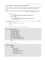
8.5.
Grounding Point Cabling
As the operational grounding concept of the Kontron TRACe-LP1 calls for a ground point connection of the chassis to
external ground, there must always be a ground connection to the chassis.
This is accomplished via the ground point indicated by the ground symbol on the operational side of the Kontron
TRACe-LP1, it is a threaded blind stud which accepts an M4 screw or bolt for attaching external ground cabling to the
Kontron TRACe-LP1. This grounding wire must be connected to the vehicle’s chassis or a central grounding point.
Maximum permissible ingress of a screw into the blind nut is 8 mm.
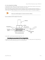
Figure 3: Assembly of the Grounding Point Connection
Screw the M4 nut with the recommended torque: 1N.m +/-0.1.
Grounding Recommendation for Power Supply Cable.
Each shield end of power cable shall be connected to external ground (same as chassis ground). Automatically done
on M12 connector side. Shall be done by user for the other cable’s end.
Summary of Contents for Kontron TRACe-LP1
Page 1: ...USER GUIDE www kontron com Kontron TRACe LP1 Gateway SD DT G74 7e February 2019 ...
Page 6: ...Kontron TRACe LP1 Gateway User Guide SD DT G74 7e www kontron com 6 ...
Page 21: ...Kontron TRACe LP1 Gateway User Guide SD DT G74 7e www kontron com 21 ...
Page 29: ...Kontron TRACe LP1 Gateway User Guide SD DT G74 7e www kontron com 29 ...


