background image

For more information, Please access to our service web site(http://itself.sec.samsung.co.kr)

AIR CONDITIONER

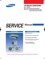
THE FEATURE OF PRODUCT

SYSTEM AIR CONDITIONER

Basic : DH24BTA 
Model : EH035EAV/EH052EAV/EH070EAV
Model Code : EH035EAV/EH052EAV/EH070EAV

UH035EAV/UH052EAV/UH070EAV


Built-in Duct Type


High Performance & Energy Saving


Long Piping(Length & Height)


Long Ambient Operation(In Low Temp.)


:  Up to -10˚C(Heating), Up to -5˚C(Cooling)


Eco-friendly Product 


  (Lead-Free, RoHS, WEEE)

EH035EAV/EH052EAV/EH070EAV

UH052EAV

UH070EAV

UH035EAV

25888A(1)_co.indd   1

2006-04-14   ソタネト 2:16:03

Summary of Contents for UH035EAV Series

Page 1: ...Basic DH24BTA Model EH035EAV EH052EAV EH070EAV Model Code EH035EAV EH052EAV EH070EAV UH035EAV UH052EAV UH070EAV Built in DuctType High Performance Energy Saving Long Piping Length Height Long Ambient Operation In LowTemp Up to 10 C Heating Up to 5 C Cooling Eco friendly Product Lead Free RoHS WEEE EH035EAV EH052EAV EH070EAV UH052EAV UH070EAV UH035EAV ...

Page 2: ...ications 2 5 13 Alignment and Adjustments 3 1 3 1 Indoor Display Error and Check Method 3 1 3 2 Outdoor LED Error Display and Check Method 3 4 3 3 Setting Option Setup Method 3 5 14 Disassembly and Reassembly 4 1 4 1 Indoor Unit 4 1 4 2 Outdoor Unit 4 14 15 Exploded Views and Parts List 5 1 5 1 Indoor Unit 5 1 5 2 Outdoor Unit 5 5 5 3 Ass y Control Out 5 11 16 Electrical Parts List 6 1 17 Wiring D...

Page 3: ... 10 12 Troubleshooting 12 1 12 1 Items to be checked first 12 1 12 2 Fault Diagnosis by Symptom 12 2 12 3 PCB Inspection Method 12 19 12 4 Main Part Inspection Method 12 21 13 Block Diagram 13 1 13 1 Indoor Unit 13 1 13 2 Outdoor Unit 13 2 14 Reference Sheet 14 1 14 1 Index for Model Name 14 1 14 2 Low Refrigerant Pressure Distribution 14 2 14 3 Pressure Capacity mark 14 3 14 4 Q A for Non trouble...

Page 4: ...in order to avoid a hazard The air conditioner must be plugged into an independent circuit if applicable or connect the power cable to the auxiliary circuit breaker An all pole disconnection from the power supply must be incorporated in the fixed wiring with a contact opening of 3mm Do not extend an electric cord to the air conditioner The air conditioner must be plugged in after you complete the ...

Page 5: ...ntacts with your skin it can cause skin injury The package of the air conditioner should be recycled or disposed of properly for environmental reasons 1 5 Others Never store or load the air conditioner upside down or sideways to prevent the damage to the compressor Young children or infirm persons should be always supervised when they use the air conditioner Max current is measured according to IE...

Page 6: ...oom cool with highly energy saving and arises the efficiency of air conditioner Long Piping Length Height It can give the benefit to the installers and aries the reliability of the air conditioner EH035EAV Max 20m Long 12m Height EH052 070EAV Max 30m Long 15m Height Long Ambient Operation In Low Temperature It can arise the reliability and the capacity of the air conditioner especially operated in...

Page 7: ...hxHeightxDepth mm 900x199x600 790x548x285 inch 35 4x7 8x15 4 31 1x21 6x11 2 Weight Net kg 26 35 5 Compressor Type Rotary G4C090LU2ER Motor Type Hermetic Rated Output W 853 Oil Type POE Blower Type Sirocco Propeller Motor Type Resin Steel Resin Steel Rated Output W 30 40 Piping Pipe O D Size Liquid mm inch xL m ø6 35 1 4 x7 5 Gas mm inch xL m ø12 7 1 2 x7 5 Connection Method Flare Between Height m ...

Page 8: ... 0 96 8 Size Outer Dimension WidthxHeightxDepth mm 1 100x199x600 880x638x310 1 100x199x600 880x798x310 inch 43 3x7 8x23 6 34 6x25 1x12 2 43 3x7 8x23 6 34 6x31 4x12 2 Weight Net kg 31 50 31 57 Compressor Type G8T200FU1EW G8T260FU1EW Motor Type BLDC BLDC Rated Output W 2 000 2 470 Oil Type POE Blower Type Sirocco Propeller Sirocco Propeller Motor Type Resin Steel Steel Resin Steel Steel Rated Output...

Page 9: ...EH070EAV DH24BT Basic Design Indoor Unit Outdoor Unit Net Weight Indoor Unit 31 0kg 34 0kg Outdoor Unit 57 0kg 74 0kg Outer Dimension WxHtxD Indoor Unit 1 100x199x600mm 1 100x199x600mm Outdoor Unit 880x798x310mm 880x798x310mm Noise Indoor Unit 42dB 42dB Outdoor Unit 60dB 59dB ...

Page 10: ...UCCIONES ISTRUZIONI PER L USO MANUAL DE INSTRUÇ Õ ES MANUEL D UTILISATION GEBRAUCHSANWEISUNG Splut type R oom Air Conditioner Aire acondicionado domé stico sistema Split Condizionatore d aria per ambienti ad unità Separate Aparelho de ar condicionado tipo Split Climatiseur de type sé paré Geteilte raumklimaanlage OWNER S INSTRUCTIONS SPLIT TYPE R OOM AIR CONDITIONER OWNER S INSTRUCTIONS MANUAL DE ...

Page 11: ...oller Accessories Item Descriptions Code No Q TY Remark Wireless remote controller DB93 00251G 1 Battery DB47 90024A 2 Remote control holder DB61 00204A 1 STS 2S 2x10 tapped screw 6002 000581 2 Owner s instructions DB98 05156A 1 Installation manual DB98 05184A 1 2 6 ...

Page 12: ...ble tie DB65 10088B 2 Cable clamp DB65 10074E 5 M4x16 tapped screw 6002 000474 7 Indoor unit power drawing cable DB39 00221A 1 Communication cable of the wired remote controller DB39 00933A 1 Wire joint DB39 90020A 1 Owner s instructions DB98 15731A 1 Installation manual DB98 15770A 1 Wired Remote Controller Accessories Product Specifications ...

Page 13: ...mperature sensor in the indoor unit Open Short X X X X Error of heat exchanger sensor in the indoor unit X X X Error of the outdoor temperature sensor Error of the condensor temperature sensor Error of the discharge temperature sensor X X X Indoor and outdoor unit time out Abnormal data reception more than 60 packet Indoor unit is not connected Communication error between the outdoor unit Main Inv...

Page 14: ...n failure Inverter DC peak error Inverter DC Link voltage 150V or less 410V or more Inverter Compressor rotation error Inverter Electric current error Inverter DC Link sensor error Inverter EEPROM READ WRITE error Inverter Inverter zerocrossing error Setting the outdoor unit capacity option error X X Detection of the float switch X X X Error of setting option switches for optional accessories X X ...

Page 15: ...PEN SHORT ERROR Inverter Compressor Discharge Temp sensor Error OPEN SHORT ERROR Indoor Float S W 2nd Detection Self Diagnosys Error Outdoor unit Indoor unit Communication wire Voltage Detection Outdoor unit Refrigerant Full Leakage Gas Leak Outdoor door Fan Error Inverter Inverter Comp Start Failure Outdoor Unit Protection Control Error Inverter DC PEAK Error Inverter DC LINK Voltage 150V below 4...

Page 16: ...rge temperature sensor error Dual Single 11 Current sensor error 12 Compressor Limit error 13 Coil temperature sensor error Dual Single 14 1min Time out Communication 15 Fan error 16 OTP error 17 Compressor rotation error 18 Operation condition secession Dual only 19 DC Link voltage sensor error 20 I_Trip error PFC Over current 21 GAS Leak error Dual Single 22 AC Line Zero Cross Signal out 23 Powe...

Page 17: ...peatedly Push the button to set the display panel to Every time you push the button the display panel reads repeatedly Push the button to set the display panel to Every time you push the button the display panel reads repeatedly 3 3 Setting Option Setup Method ex Option No Step 1 Enter the Option Setup mode 1st Take out the batteries of remote control 2nd Press the temperature button simultaneousl...

Page 18: ... the display part to and check the display part The display part shows Press the Mode Selection key to set the display part to and check the display part The display part shows Step 4 Pressing the ON OFF button When pressing the operation ON OFF key with the direction of remote control for unit the sound Ding or Diriring is heard and the OPERATION ICON lamp of the display is flickering at the same...

Page 19: ...n Samsung Electronics Alignment and Adjustments OPTION ITEMS SEG1 SEG2 SEG3 SEG4 SEG5 SEG6 SEG7 SEG8 SEG9 SEG10 SEG11 SEG12 EH035EAV 0 1 5 7 7 3 1 5 8 1 d b EH052EAV 0 1 5 7 7 3 1 9 8 1 3 9 EH070EAV 0 1 5 7 7 4 1 c 8 2 7 8 MODEL REMOCON 3 7 ...

Page 20: ...ditioner and remove the power cord before repairing the unit No Parts Procedure Remark 1 Motor Blower 1 Disassemble the Cabinet Top Motor Unscrew 8 screws 2 Disassemble 2 Cover Blower Uppers After unscrewing 2 screws Disassemble the Cover Blower Upper with pushing its hook 3 Disassemble the Cover Control Unscrew 2 screws 4 1 EH035EAV ...

Page 21: ...connected to the inside of PCB and connected to the Capacitor 5 Disassemble the Motor earth wire connected to the Partition Unscrew a screw 6 Disassemble the band Motor for fixing the Motor Unscrew 2 screws 7 After disassembling the Motor and Blower for the set disassemble the Blower by use of 3mm wrench ...

Page 22: ...bly and Reassembly 4 3 No Parts Procedure Remark 2 Drain Pan 1 Disassemble the Cabinet Top Evap Unscrew 11 screws 2 Disassemble the Bracket Outlet Sub that fixes the Drain Pan equipped on the front of the set Unscrew 6 screws 3 Disassemble the Drain Cushion from the set ...

Page 23: ...the Cover Control 1 3 and the Drain Pan 2 1 2 2 2 3 1 Disassemble the Cover Pipe that fixes the high low pressure Pipe Unscrew 2 screws 2 Disassemble the refrigerant temperature sensor Inlet air temperature sensor and EEV wire that connected to the inside of PCB 3 Disassemble the Support Evap LF that fixes the Evaporator Unscrew 2 screws 4 Disassemble the Support Evap RH Unscrew 2 screws ...

Page 24: ...res connected to the inside of PCB 2 In case of disassembling the PCB separately disassemble the PCB from the case with pushing the hook after unscrewing the screw Unscrew 1 screw 3 In case of disassembling the Capacitor separately disassemble the Capacitor from the Case 4 In case of disassembling the Case Control disassemble the Case Control from the set after unscrewing the screw connected to th...

Page 25: ...ng the Trans Power unscrew the screw fixing on the Case Disassemble if after disassembling the case PCB 4 4 5 Bracket Outlet 1 Disassemble the Bracket Outlet assembled on the Cabinet Unscrew 10 screws 4 6 Samsung Electronics Disassembly and Reassembly ...

Page 26: ...s Disassembly and Reassembly No Parts Procedure Remark 1 Filter 1 Pull out the Filter as picture 1 or picture 2 2 If it is necessary after disassembling 8 indicating screws detach the Bracket Filter EH052EAV EH070EAV 4 7 ...

Page 27: ...he procedure of disassembling the Filter is just as the above 2 Blower Motor 1 After disassembling 13 indicating screws detach Ass y Cabinet Top Motor 2 After disassembling 3 indicating screws detach Ass y Case Blower Upper Press the pothook of the Case Blower and detach Ass y Case Blower Upper 4 8 Samsung Electronics ...

Page 28: ...ter disassembling 2 indicating screws detach the Cover Control 4 Detach the Motor Wire Connected to PCB and Capacitor 5 After disassembling the indicating screws detach the wire connected to the Partition 6 After disassembling 2 indicating screws detach the Ass y Band Motor 4 9 ...

Page 29: ...and Blowers detach the Blowers from the axis of the Motor by 3mm inner hexagon spanner 3 Drain Pan 1 After disassembling 15 indicating screws detach Ass y Cabinet Top Evap 2 After disassembling 6 indicating screws detach the Bracket Outlet 3 Detach the Drain Pan 4 10 Samsung Electronics ...

Page 30: ...aporator 1 After disassembling 2 indicating screws detach Ass y Cover Pipe 2 Detach the Sensor from the Control Box including 2 Sensors 3 After disassembling 2 indicating screws detach Ass y Support Evap LF 4 After disassembling 2 indicating screws detach Ass y Support Evap RH Disassembly and Reassembly 4 11 ...

Page 31: ...rol 1 Detach all the wires connected to the PCB 2 If only the disassembly of PCB required press the Pothook and detach the PCB from the set 3 If only the disassembly of Capacitor is required detach it from the set 4 If only the disassembly of Case Control is required detach it from the set after disassembling 2 indicating screws Disassembly and Reassembly 4 12 Samsung Electronics ...

Page 32: ... Parts Procedure Remark 5 Detach the Transformer after disassembling 2 indicating screws Work is possible after disassembling the Case PCB 6 Ass y Bracket Outlet 1 After disassembling 16 indicating screws detach Ass y Bracket Outlet Disassembly and Reassembly 4 13 ...

Page 33: ...e Cover Side 2 Loosen each 3 fixing screws on both right and left Cabinet Side edges and a fixing screw on the Cabinet Front lower to detach the Cabinet Front 3 Detach the Cabinet Front like the picture on the right side 4 Loosen 1 screw fixed to assemble Plate Control Out with Cabinet Side RH UH035EAV 4 14 ...

Page 34: ...g Electronics No Parts Procedure Remark 5 Loosen 2 fixing screws on the rear side of Cabinet Side RH 6 Loosen 3 screws fixed to assemble Bracket Valve with Cabinet Side RH 7 Loosen 2 fixing screws of Cabinet Side LF Disassembly and Reassembly 4 15 ...

Page 35: ...embly No Parts Procedure Remark 2 Ass y Control Out 1 Detach the Motor Wire from the PCB of Ass y Control Out 2 Detach several connectors from the PCB of Ass y Control Out 3 Detach 2 Connect Wires from Reactor 4 Loosen 1 screw fixed to assemble Ass y Control Out with Partition 4 16 ...

Page 36: ...n both inlet and outlet with welding torch 3 Detach the Heat Exchanger 5 Ass y Valve 4 Way Ass y Valve EEV 1 Loosen 4 bolts fixed to assemble Valve Service with Bracket Valve like the picture on the right side 2 Disassemble the pipes assembled the suction and discharge sides of the Compressor with welding torch 6 Compressor 1 Loosen the Nut of Terminal Cover 2 Detach the Terminal Cover and detach ...

Page 37: ... Work 1 Loosen 1 fixing screw of the Cover Control and detach the Cover Control 2 Loosen fixing screws and detach the Cabinet Upper 3 Loosen 1 screw fixed to assemble Control Box with Cabinet Side RH 4 Loosen 6 fixing screws and detach the Cabinet Side RH UH052EAV Disassembly and Reassembly 4 18 ...

Page 38: ...rating Instructions and Installation Samsung Electronics No Parts Procedure Remark 5 Loosen 2 screws fixed on the Guide Condenser 6 Loosen fixing screws of the Cabinet Front Disassembly and Reassembly 4 19 ...

Page 39: ...eft handed 2 Detach the Fan Propeller 3 Loosen 4 fixing screws to detach the Motor 4 Disconnect the wire between Ass y Control Out and Motor 5 Loosen 2 fixing screws and detach the Bracket Motor 3 Ass y Control Out 1 Detach several connectors from the Ass y Control Out 2 Detach several connectors from the PCB of Ass y Control Out 3 Pull up the Ass y Control Out Disassembly and Reassembly 4 20 ...

Page 40: ...2 Loosen fixing screw 3 Disassemble the pipes in both inlet and outlet with welding torch 4 Detach the Heat Exchanger 5 Compressor 1 Loosen the fixing nut and detach the Compressor Lead Wire 2 Disassemble the Felt Comp Sound 3 Loosen the 3 bolts at the bottom of Compressor like the picture on the right side Disassembly and Reassembly 4 21 ...

Page 41: ...rk 1 Loosen 1 fixing screw of the Cover Control and detach the Cover Control 2 Loosen each 8 fixing screws and detach the Cabinet Upper 3 Loosen 1 screw fixed to assemble Control Box with Cabinet Side RH 4 Loosen fixing screws and detach the Cabinet Side RH UH070EAV Disassembly and Reassembly 4 22 ...

Page 42: ...rating Instructions and Installation Samsung Electronics No Parts Procedure Remark 5 Loosen 2 screws fixed on the Guide Condenser 6 Loosen fixing screws of the Cabinet Front Disassembly and Reassembly 4 23 ...

Page 43: ...e Nut Flange like the picture on the right side Turn clockwise because the screw is left handed 2 Detach the Fan Propeller 3 Loosen 4 fixing screws to detach the Motor 4 Disconnect the wire between Ass y Control Out and Motor 5 Loosen 2 fixing bolts and detach the Bracket Motor Disassembly and Reassembly 4 24 ...

Page 44: ...from the Ass y Control Out 2 Detach several connectors from the PCB of Ass y Control Out 3 Pull up the Ass y Control Out 4 Heat Exchanger 1 Release the refrigerant at first 2 Loosen fixing screw on both sides 3 Disassemble the pipes in both inlet and outlet with welding torch 4 Detach the Heat Exchanger Disassembly and Reassembly 4 25 ...

Page 45: ...ronics No Parts Procedure Remark 5 Compressor 1 Loosen the fixing nut and detach the Compressor Lead Wire 2 Disassemble the Felt Comp Sound 3 Loosen the 3 bolts at the bottom of Compressor like the picture on the right side Disassembly and Reassembly 4 26 ...

Page 46: ...MEMO Samsung Electronics 4 27 ...

Page 47: ...Samsung Electronics 5 1 5 Exploded Views and Parts List 5 1 Indoor Unit 23 8 13 9 12 14 2 16 18 17 1 6 15 21 11 24 4 5 22 10 3 8 7 19 20 23 4 23 7 23 5 23 6 23 3 23 8 23 1 23 2 EH035EAV ...

Page 48: ... RH ASS Y 1 SA 15 DB94 00768A ASS Y PARTITION ASS Y 1 SA 16 DB61 02282A BRACKET MOTOR SGCC M T2 0 1 SA 17 DB99 00669A ASS Y BAND MOTOR SINYA 1 SNA 18 DB31 00312A MOTOR FAN SINYA SSR PID 1 SA 19 DB67 00565A BLOWER ASS Y ABS TORSIONAL BUSH 2 SA 20 DB90 01947A ASS Y CASE BLOWER UPPER ASS Y 2 SA 21 DB90 01948A ASS Y CASE BLOWER BOTTOM ASS Y 2 SA 22 DB94 00716A ASS Y DRAIN PAN ASS Y 1 SNA 23 DB93 03321...

Page 49: ...msung Electronics 5 3 8 10 9 13 11 32 16 22 21 27 28 20 23 24 19 17 3 18 26 25 5 8 4 30 30 1 30 6 30 5 30 2 35 30 4 30 3 12 29 33 34 34 6 7 14 31 15 2 1 36 EH052EAV EH070EAV Exploded Views and Parts List ...

Page 50: ... ASS Y SGCC M T1 0 1 1 SA 17 DB61 02282A BRACKET MOTOR SGCC M T2 0 1 1 SA 18 DB97 03800A ASS Y BAND MOTOR SINYA ASS Y 1 1 SA 19 DB31 00314A MOTOR SINYA 50Hz YSK140 60 4PG 1 1 SA 20 DB66 01007A MOTOR SHAFT SINYA 1 1 SA 21 DB94 00759A MOLD BEARING ASS Y 1 1 SA 22 DB67 00581A CAP BEARING SGCC M T0 8 1 1 SA 23 DB73 00285A RUBBER SHAFT CR V0 1 1 SA 24 DB96 04902A COUPLER ASS Y 1 1 SA 25 DB67 00565A BLO...

Page 51: ...Samsung Electronics 5 5 5 2 Outdoor Unit 1 3 16 15 7 20 25 24 9 8 4 23 18 6 14 13 19 11 12 21 10 22 17 17 3 19 2 19 1 20 2 20 1 20 3 17 4 17 2 17 1 17 5 5 2 UH035EAV ...

Page 52: ... P SC 90073T 1 SA 16 DB64 00992A HANDLE LF PP SC 90073R 1 SA 17 G4C090LU2ER COMPRESSOR ROTARY BLDC 1 SA 17 1 DB73 00070A GROMMET ISOLATOR NR 3 SA 17 2 DB60 30028A SCREW MACHINE M8 3 SA 17 3 DB60 30018A NUT FLANGE M5 1 SA 17 4 DB63 10165D COVER TERMINAL PBT G F 15 1 SA 17 5 DB63 20003A GASKET EPDM 1 SA 18 DB63 01435A FELT COMP SOUND FELT EVAR 1 SA 19 DB99 00726B ASS Y VALVE 4WAY ASS Y 1 SA 19 1 DB6...

Page 53: ...Samsung Electronics 14 8 10 17 22 21 4 1 2 3 13 12 11 20 19 9 7 16 1 15 2 15 15 4 18 1 15 3 15 1 16 18 5 6 UH052EAV Exploded Views and Parts List 5 7 ...

Page 54: ...3 DB63 00343A GUARD COND SC 90073T 1 SA 14 DB90 01881A ASS Y CABI UPPER ASS Y 1 SA 15 G8T200FU1EW COMPRESSOR ROTARY 1 SA 15 1 DB73 00067A GROMMET ISOLATOR NR 3 SA 15 2 DB60 30028A NUT WASHER M8 3 SA 15 3 DB60 30018A NUT FLANGE M5 1 SA 15 4 DB63 10165D COVER TERMINAL PBT 1 SA 16 DB99 00711A ASS Y 4WAY V V ASS Y 1 SA 16 1 DB62 02285A VALVE SERVICE 1 2 1 SNA 17 DB99 00708A ASS Y VALVE EEV ASS Y 1 SA ...

Page 55: ...Samsung Electronics 14 8 10 17 1 4 13 12 11 9 19 7 3 2 16 1 18 1 16 18 5 20 6 15 2 15 15 4 15 3 15 1 22 21 UH070EAV Exploded Views and Parts List 5 9 ...

Page 56: ...13 DB63 30027C GUARD COND SC 90073T 1 SA 14 DB90 00569G ASS Y CABI UPPER ASS Y 1 SA 15 G8T260FU1EW COMPRESSOR ROTARY 1 SA 15 1 DB73 00067A GROMMET MOUNT NR 3 SNA 15 2 DB60 30028A NUT WASHER M8 3 SA 15 3 DB60 30018A NUT FLANGE M5 1 SA 15 4 DB63 10165D COVER TERMINAL PBT 1 SA 16 DB99 00710B ASS Y 4WAY V V ASS Y 1 SA 16 1 DB62 02342A VALVE SERVICE 5 8 1 SNA 17 DB99 00709A ASS Y VALVE EEV ASS Y 1 SA 1...

Page 57: ...Samsung Electronics 5 11 5 3 Ass y Control Out UH035EAV DB93 03453A ...

Page 58: ...M T0 6 1 SA 12 DB62 02332P SEAL CASE CONTROL BASE FOAM PU BLACK 1 SNA 13 6002 000555 SCREW TAPPING M4xL25 PH ZPC YEL 1 SNA 14 DB65 00179C TERMINAL BLOCK DAF 6P 1 SA 15 DB93 03662A ASS Y PCB DISPLAY FR 1 35x25 1 SA 16 DB61 02543A CASE DISPLAY PCB ABS V0 T2 0 1 SA 17 DB61 00171A HOLDER WIRE CLAMP ABS 2 SA 18 6001 001054 SCREW TAPPING M4xL10 TH ZPC YEL 4 SNA 19 DB81 00547B INSULATOR MICA 1 SNA 20 DB3...

Page 59: ...Samsung Electronics Ass y Control Out cont UH052EAV DB93 03665D UH070EAV DB93 03665E 5 13 ...

Page 60: ... ASS Y PCB MAIN PCB 2L 1 SA DB93 03545E ASS Y PCB MAIN PCB 2L 1 SA 14 DB93 03546A ASS Y PCB SUB EMI PCB 2L 1 SA DB93 03546D ASS Y PCB SUB EMI PCB 2L 1 SA 15 DB93 03662A ASS Y PCB DISPLAY PCB 1L 1 1 SA 16 DB98 17991A ASS Y INSULATOR MICA MICA 2 2 SNA 17 6002 000630 SCREW TAPPING PH M3 L8 3 3 SNA 18 DB91 00306A ASS Y SCREW MACHINE PH M3 L16 3 3 SNA 19 DB91 00307A ASS Y SCREW MACHINE PH M4 L16 4 4 SN...

Page 61: ... Y5V 2012 1 SNA C307 2203 000192 C CER CHIP 100nF 80 20 50V Y5V 2012 1 SNA C311 2203 000257 C CER CHIP 10nF 10 50V X7R 1608 1 SNA C312 2203 000189 C CER CHIP 100nF 80 20 25V Y5V 1608 1 SNA C313 2203 000189 C CER CHIP 100nF 80 20 25V Y5V 1608 1 SNA C314 2203 000192 C CER CHIP 100nF 80 20 50V Y5V 2012 1 SNA C315 2203 000192 C CER CHIP 100nF 80 20 50V Y5V 2012 1 SNA C316 2203 000192 C CER CHIP 100nF ...

Page 62: ...CABLE 1WALL 2P 1R 7 92mm STRAIGHT SN BLU 1 SNA CN72 3711 000203 HEADER BOARD TO CABLE 1WALL 2P 3P 1R 7 92mm STRAIGHT SN WHT 1 SNA CN74 3711 003406 HEADER BOARD TO CABLE 1WALL 2P 1R 7 92mm STRAIGHT SN YEL 1 SNA CN75 3711 003405 HEADER BOARD TO CABLE 1WALL 2P 1R 7 92mm STRAIGHT SN BLK 1 SNA CN77 3711 003407 HEADER BOARD TO CABLE 1WALL 2P 1R 7 92mm STRAIGHT SN RED 1 SNA CN78 3711 000262 HEADER BOARD ...

Page 63: ...5P 2 9x1 6mm PLASTIC 1 SNA 3 716 4 284V 256mW 2 5mA TP IC04 DB09 00395B IC MICOM MB90F823 80 P 5 V 24 MHz STM 0519 BS 1 SNA 24 16 QFP QFP 14x20 mm 16 40 85 IC05 0506 000175 TR ARRAY 2003 NPN 7 1W SOP 16 ST 1000 1 SNA IC06 0506 000175 TR ARRAY 2003 NPN 7 1W SOP 16 ST 1000 1 SNA IC07 0506 000175 TR ARRAY 2003 NPN 7 1W SOP 16 ST 1000 1 SNA IC08 0506 000175 TR ARRAY 2003 NPN 7 1W SOP 16 ST 1000 1 SNA ...

Page 64: ... R CHIP 120ohm 5 1 8W TP 2012 1 SNA R201 2007 000468 R CHIP 1Kohm 5 1 8W TP 2012 1 SNA R202 2007 000686 R CHIP 3 3Kohm 5 1 8W TP 2012 1 SNA R204 2007 000300 R CHIP 10Kohm 5 1 8W TP 2012 1 SNA R205 2007 000468 R CHIP 1Kohm 5 1 8W TP 2012 1 SNA R206 2007 000468 R CHIP 1Kohm 5 1 8W TP 2012 1 SNA R207 2007 000468 R CHIP 1Kohm 5 1 8W TP 2012 1 SNA R302 2007 000300 R CHIP 10Kohm 5 1 8W TP 2012 1 SNA R30...

Page 65: ...012 1 SNA R613 2007 000872 R CHIP 4 7Kohm 5 1 8W TP 2012 1 SNA R803 2007 000300 R CHIP 10Kohm 5 1 8W TP 2012 1 SNA R804 2007 000300 R CHIP 10Kohm 5 1 8W TP 2012 1 SNA R805 2007 000477 R CHIP 1Mohm 5 1 8W TP 2012 1 SNA R901 2007 000766 R CHIP 330ohm 5 1 8W TP 2012 1 SNA R902 2007 000468 R CHIP 1Kohm 5 1 8W TP 2012 1 SNA R903 2007 000300 R CHIP 10Kohm 5 1 8W TP 2012 1 SNA R911 2007 000300 R CHIP 10K...

Page 66: ...00154 VARISTOR 460Vdc 2500A 17 5x7 5mm TP 1 SNA X301 2802 001179 RESONATOR CERAMIC 4MHz 0 5 BK 8x3x5 5mm 1 SNA X701 2301 001220 C FILM LEAD PPF 100nF 10 275V BK 18x6x12 15 1 SNA X702 2301 001220 C FILM LEAD PPF 100nF 10 275V BK 18x6x12 15 1 SNA DB62 03085A HEAT SINK A6063 25 15 15 SSEC 1 SNA DB68 02809A LABEL BAR CODE W170 L115 FOR PACKING CASE 1 SNA Location No Code No Description Specification Q...

Page 67: ... SNA C118 2401 002300 C AL 47uF 20 50V GP TP 6 3x11 5 1 SNA C119 2401 000832 C AL 220uF 20 25V GP TP 8x11 5 5 1 SNA C121 2203 000192 C CER CHIP 100nF 80 20 50V Y5V 2012 1 SNA C122 2203 000477 C CER CHIP 1000NF 80 20 16V Y5V TP 2012 1 SNA C123 2401 000303 C AL 100uF 20 25V GP TP 6 3x11 5 1 SNA C201 2203 000257 C CER CHIP 10nF 10 50V X7R 1608 1 SNA C202 2203 000189 C CER CHIP 100nF 80 20 25V Y5V 160...

Page 68: ... 6 3x11 2 5 1 SNA C509 2203 000189 C CER CHIP 100nF 80 20 25V Y5V 1608 1 SNA C517 2203 000189 C CER CHIP 100nF 80 20 25V Y5V 1608 1 SNA C520 2203 000189 C CER CHIP 100nF 80 20 25V Y5V 1608 1 SNA C521 2203 000257 C CER CHIP 10nF 10 50V X7R 1608 1 SNA C522 2203 000189 C CER CHIP 100nF 80 20 25V Y5V 1608 1 SNA C523 2203 000189 C CER CHIP 100nF 80 20 25V Y5V 1608 1 SNA C524 2203 000189 C CER CHIP 100n...

Page 69: ...C 1 44A IC12 0604 001172 PHOTO COUPLER TR 100 300 200mW SOP TP 1 SNA IC13 1203 002948 IC POSI ADJUST REG TL431ACD SOP 8P 4 9x3 9mm PLASTIC 36V 1 5W 1 SNA 0TO 70C 150mA 2 44 2 55V TP IC16 DB95 00594A ASS Y VOLTAGE REGULATOR MH080FXEA4 KIA78M05 KA78M05 1 SNA IC19 DB95 00594A ASS Y VOLTAGE REGULATOR MH080FXEA4 KIA78M05 KA78M05 1 SNA IC21 1202 000104 IC VOLTAGE COMP 393 SOP 8P 150MIL DUAL 36V CMO 1 SN...

Page 70: ...P 14 3Kohm 1 1 4W TP 3216 1 SNA R201 2007 002667 R CHIP 90 9Kohm 1 1 4W TP 3216 1 SNA R202 2007 002667 R CHIP 90 9Kohm 1 1 4W TP 3216 1 SNA R203 2007 002667 R CHIP 90 9Kohm 1 1 4W TP 3216 1 SNA R204 2007 002667 R CHIP 90 9Kohm 1 1 4W TP 3216 1 SNA R205 2007 000263 R CHIP 1 82Kohm 1 1 8W TP 2012 1 SNA R206 2007 000263 R CHIP 1 82Kohm 1 1 8W TP 2012 1 SNA R207 2007 000080 R CHIP 2Kohm 5 1 10W TP 160...

Page 71: ...1 SNA R472 2007 000074 R CHIP 100ohm 5 1 10W TP 1608 1 SNA R509 2007 000076 R CHIP 330ohm 5 1 10W TP 1608 1 SNA R510 2007 000076 R CHIP 330ohm 5 1 10W TP 1608 1 SNA R515 2007 000090 R CHIP 10Kohm 5 1 10W TP 1608 1 SNA R516 2007 000090 R CHIP 10Kohm 5 1 10W TP 1608 1 SNA R517 2007 000090 R CHIP 10Kohm 5 1 10W TP 1608 1 SNA R536 2007 000109 R CHIP 1Mohm 5 1 10W TP 1608 1 SNA R537 2007 000090 R CHIP ...

Page 72: ...E AS18BPBX 18 MG620023 230V 50Hz 1 SNA 1015 18 AWG 4way valve WIRE COMP DB39 00608H CONNECT WIRE COMP SH12BPB 1015 16 AWG AWG 3 290 280 270 1 SNA red blue yellow 16 MG620877 250V 29 WIRE PCB DB39 01194B CONNECT WIRE AS12 09 BPB 1007 26 AWG 7P 150 WHT 1 SNA SMH200 07 WHT YBH200 07WHT BK 230V 50Hz WIRE REACTOR DB39 00998F CBF LEAD WIRE AS12 09 BPBX 200 260 600V AWG 16 1 SNA WHIT YEL CORE TR29G5A XTA...

Page 73: ...5V 2012 1 SNA C110 2401 000832 C AL 220uF 20 25V GP TP 8x11 5 5 1 SNA C112 2203 000192 C CER CHIP 100nF 80 20 50V Y5V 2012 1 SNA C113 2203 005261 C CER CHIP 1000nF 10 25V X7R 3216 1 SNA C114 2401 000832 C AL 220uF 20 25V GP TP 8x11 5 5 1 SNA C116 2203 000192 C CER CHIP 100nF 80 20 50V Y5V 2012 1 SNA C117 2203 000192 C CER CHIP 100nF 80 20 50V Y5V 2012 1 SNA C118 2401 002300 C AL 47uF 20 50V GP TP ...

Page 74: ...2 1 SNA C416 2203 000126 C CER CHIP 1 2nF 10 50V X7R TP 2012 1 SNA C417 2203 000192 C CER CHIP 100nF 80 20 50V Y5V 2012 1 SNA C418 2203 000192 C CER CHIP 100nF 80 20 50V Y5V 2012 1 SNA C419 2203 000609 C CER CHIP 22nF 10 50V X7R TP 2012 1 SNA C420 2203 000609 C CER CHIP 22nF 10 50V X7R TP 2012 1 SNA C421 2401 002274 C AL 220uF 20 35V WT TP 10x12 5 5 1 SNA C422 2306 000123 C FILM LEAD PPF 100nF 5 6...

Page 75: ...nF 80 20 25V Y5V 1608 1 SNA C703 2203 000189 C CER CHIP 100nF 80 20 25V Y5V 1608 1 SNA C704 2203 000189 C CER CHIP 100nF 80 20 25V Y5V 1608 1 SNA C705 2203 000189 C CER CHIP 100nF 80 20 25V Y5V 1608 1 SNA C706 2203 000192 C CER CHIP 100nF 80 20 50V Y5V 2012 1 SNA C707 2203 000189 C CER CHIP 100nF 80 20 25V Y5V 1608 1 SNA C708 2203 000189 C CER CHIP 100nF 80 20 25V Y5V 1608 1 SNA C709 2401 003036 C...

Page 76: ... 23 TP 1 SNA EEPROM DATA DB46 00014B SOFTWARE PACK EEPROM EEPROM UH052EAV EUROPE CEILING HEX 18K 1 SNA IC11 1203 003527 IC PWM CONTROLLER TOP243 DIP 7P 9 83x6 6mm PLASTIC 0 3 700V 1 SNA 25W 40to 150C 1 44A IC12 0604 001172 PHOTO COUPLER TR 100 300 200mW SOP TP 1 SNA IC13 1203 002948 IC POSI ADJUST REG TL431ACD SOP 8P 4 9x3 9mm PLASTIC 36V 1 5W 1 SNA 0TO 70C 150mA 2 44 2 55V TP IC16 DB95 00594A ASS...

Page 77: ... 230V 50Hz 3 96mm 100 UL101 L W POWER R DB39 00765S HARNESS POWER N AS24 18 BPB 1015 AWG 14 150 BRN 14 1 SNA ST730574 3 TP 230V 50Hz 2 5mm 120 UL1 LED1 DB98 16601A ASS Y LED RED 1 SNA LED2 DB98 16600A ASS Y LED GREEN 1 SNA LED3 DB98 16602A ASS Y LED YEL 1 SNA PCB DB41 00432A PCB MAIN BOARD AS18BPB FR 4 2 1 0 1 6T 220 180 2MICOM 485 1 SNA PT02 DB26 00049A TRANS PULSE PT_50 MH080FXEA4 10 65 5 8 14 E...

Page 78: ...hm 5 1 8W TP 2012 1 SNA R303 2007 000300 R CHIP 10Kohm 5 1 8W TP 2012 1 SNA R304 2007 000300 R CHIP 10Kohm 5 1 8W TP 2012 1 SNA R305 2007 000300 R CHIP 10Kohm 5 1 8W TP 2012 1 SNA R306 2007 000300 R CHIP 10Kohm 5 1 8W TP 2012 1 SNA R307 2007 000656 R CHIP 27Kohm 5 1 4W TP 3216 1 SNA R308 2007 000656 R CHIP 27Kohm 5 1 4W TP 3216 1 SNA R311 2007 000656 R CHIP 27Kohm 5 1 4W TP 3216 1 SNA R312 2007 00...

Page 79: ...5 1 SNA R500 2007 000455 R CHIP 18Kohm 1 1 10W TP 1608 1 SNA R501 2007 000455 R CHIP 18Kohm 1 1 10W TP 1608 1 SNA R502 2007 000455 R CHIP 18Kohm 1 1 10W TP 1608 1 SNA R503 2007 000614 R CHIP 24Kohm 1 1 10W TP 1608 1 SNA R504 2007 000076 R CHIP 330ohm 5 1 10W TP 1608 1 SNA R505 2007 000076 R CHIP 330ohm 5 1 10W TP 1608 1 SNA R506 2007 000076 R CHIP 330ohm 5 1 10W TP 1608 1 SNA R507 2007 000076 R CH...

Page 80: ...TP 2012 1 SNA R708 2007 000511 R CHIP 2 4Kohm 5 1 8W TP 2012 1 SNA R709 2007 000090 R CHIP 10Kohm 5 1 10W TP 1608 1 SNA R710 2007 000090 R CHIP 10Kohm 5 1 10W TP 1608 1 SNA R711 2007 000090 R CHIP 10Kohm 5 1 10W TP 1608 1 SNA R712 2007 000090 R CHIP 10Kohm 5 1 10W TP 1608 1 SNA R713 2007 000090 R CHIP 10Kohm 5 1 10W TP 1608 1 SNA R721 2007 000763 R CHIP 330ohm 1 1 10W TP 1608 1 SNA R722 2007 00061...

Page 81: ...AY POWER 12VDC 0 9W 20000mA SPST 20mS 10mS 1 SA RY03 3501 001238 RELAY POWER DC12V 3A 250V AC 10mS 10mS 1 SNA RY04 3501 001238 RELAY POWER DC12V 3A 250V AC 10mS 10mS 1 SNA RY05 3501 001238 RELAY POWER DC12V 3A 250V AC 10mS 10mS 1 SNA RY31 3501 001248 RELAY MINIATURE 12V 11 7mA DPDT 4mS 4mS 1 SNA XTAL01 2802 001179 RESONATOR CERAMIC 4MHz 0 5 BK 8x3x5 5mm 1 SNA XTAL51 2802 001179 RESONATOR CERAMIC 4...

Page 82: ...F 80 20 50V Y5V 2012 1 SNA C113 2203 005261 C CER CHIP 1000nF 10 25V X7R 3216 1 SNA C114 2401 000832 C AL 220uF 20 25V GP TP 8x11 5 5 1 SNA C116 2203 000192 C CER CHIP 100nF 80 20 50V Y5V 2012 1 SNA C117 2203 000192 C CER CHIP 100nF 80 20 50V Y5V 2012 1 SNA C118 2401 002300 C AL 47uF 20 50V GP TP 6 3x11 5 1 SNA C119 2401 000832 C AL 220uF 20 25V GP TP 8x11 5 5 1 SNA C121 2203 000192 C CER CHIP 100...

Page 83: ...IP 1 2nF 10 50V X7R TP 2012 1 SNA C416 2203 000126 C CER CHIP 1 2nF 10 50V X7R TP 2012 1 SNA C417 2203 000192 C CER CHIP 100nF 80 20 50V Y5V 2012 1 SNA C418 2203 000192 C CER CHIP 100nF 80 20 50V Y5V 2012 1 SNA C419 2203 000609 C CER CHIP 22nF 10 50V X7R TP 2012 1 SNA C420 2203 000609 C CER CHIP 22nF 10 50V X7R TP 2012 1 SNA C421 2401 002274 C AL 220uF 20 35V WT TP 10x12 5 5 1 SNA C422 2306 000123...

Page 84: ...5V Y5V 1608 1 SNA C702 2203 000189 C CER CHIP 100nF 80 20 25V Y5V 1608 1 SNA C703 2203 000189 C CER CHIP 100nF 80 20 25V Y5V 1608 1 SNA C704 2203 000189 C CER CHIP 100nF 80 20 25V Y5V 1608 1 SNA C705 2203 000189 C CER CHIP 100nF 80 20 25V Y5V 1608 1 SNA C706 2203 000192 C CER CHIP 100nF 80 20 50V Y5V 2012 1 SNA C707 2203 000189 C CER CHIP 100nF 80 20 25V Y5V 1608 1 SNA C708 2203 000189 C CER CHIP ...

Page 85: ...N4937 600V 1A DO 41 TP 1 SNA D403 0402 000351 DIODE RECTIFIER 1N4937 600V 1A DO 41 TP 1 SNA D451 0407 000123 DIODE ARRAY DAN202K 80V 100mA CA2 3 SOT 23 TP 1 SNA EEPROM DATA DB46 00015C S W FIRMWARE EEPROM EEPROM UH070EAV 24K EUROPE HEX 1 SNA IC11 1203 003527 IC PWM CONTROLLER TOP243 DIP 7P 9 83x6 6mm PLASTIC 0 3 700V 1 SNA 25W 40to 150C 1 44A IC12 0604 001172 PHOTO COUPLER TR 100 300 200mW SOP TP ...

Page 86: ... 420 GRN 16 BK 1 SNA 230V 50Hz 2 5mm 400 L W POWER L DB39 00765R WIRE HARNESS AS24BPB 1015 16 AWG 1P 150 BRN 16 1 SNA ST730620 3 BK 230V 50Hz 3 96mm 100 UL101 L W POWER R DB39 00765S HARNESS POWER N AS24 18 BPB 1015 AWG 14 150 BRN 14 1 SNA ST730574 3 TP 230V 50Hz 2 5mm 120 UL1 LED1 DB98 16601A ASSY LED RED 1 SNA LED2 DB98 16600A ASS Y LED GREEN 1 SNA LED3 DB98 16602A ASS Y LED YEL 1 SNA PCB DB41 0...

Page 87: ... 2007 000671 R CHIP 2Kohm 5 1 8W TP 2012 1 SNA R301 2007 000023 R CHIP 120ohm 5 1 8W TP 2012 1 SNA R302 2007 000300 R CHIP 10Kohm 5 1 8W TP 2012 1 SNA R303 2007 000300 R CHIP 10Kohm 5 1 8W TP 2012 1 SNA R304 2007 000300 R CHIP 10Kohm 5 1 8W TP 2012 1 SNA R305 2007 000300 R CHIP 10Kohm 5 1 8W TP 2012 1 SNA R306 2007 000300 R CHIP 10Kohm 5 1 8W TP 2012 1 SNA R307 2007 000656 R CHIP 27Kohm 5 1 4W TP ...

Page 88: ...0Kohm 1 1 2W TP 5025 1 SNA R431 2007 008261 R CHIP 150Kohm 1 1 2W TP 5025 1 SNA R432 2007 009114 R CHIP 110Kohm 1 1 2W TP 5025 1 SNA R500 2007 000455 R CHIP 18Kohm 1 1 10W TP 1608 1 SNA R501 2007 000455 R CHIP 18Kohm 1 1 10W TP 1608 1 SNA R502 2007 000455 R CHIP 18Kohm 1 1 10W TP 1608 1 SNA R503 2007 000614 R CHIP 24Kohm 1 1 10W TP 1608 1 SNA R504 2007 000076 R CHIP 330ohm 5 1 10W TP 1608 1 SNA R5...

Page 89: ...P 5 1Kohm 5 1 10W TP 1608 1 SNA R706 2007 000511 R CHIP 2 4Kohm 5 1 8W TP 2012 1 SNA R707 2007 000511 R CHIP 2 4Kohm 5 1 8W TP 2012 1 SNA R708 2007 000511 R CHIP 2 4Kohm 5 1 8W TP 2012 1 SNA R709 2007 000090 R CHIP 10Kohm 5 1 10W TP 1608 1 SNA R710 2007 000090 R CHIP 10Kohm 5 1 10W TP 1608 1 SNA R711 2007 000090 R CHIP 10Kohm 5 1 10W TP 1608 1 SNA R712 2007 000090 R CHIP 10Kohm 5 1 10W TP 1608 1 S...

Page 90: ...917 2007 000300 R CHIP 10Kohm 5 1 8W TP 2012 1 SNA RY01 3501 001169 RELAY POWER 12VDC 0 9W 20000mA SPST 20mS 10S 1 SA RY03 3501 001238 RELAY POWER DC12V 3A 250V AC 10mS 10mS 1 SNA RY04 3501 001238 RELAY POWER DC12V 3A 250V AC 10mS 10mS 1 SNA RY05 3501 001238 RELAY POWER DC12V 3A 250V AC 10mS 10mS 1 SNA RY31 3501 001248 RELAY MINIATURE 12V 11 7mA DPDT 4mS 4mS 1 SNA XTAL01 2802 001179 RESONATOR CERA...

Page 91: ...V 1608 1 SNA C517 2203 000189 C CER CHIP 100nF 80 20 25V Y5V 1608 1 SNA C518 2203 000189 C CER CHIP 100nF 80 20 25V Y5V 1608 1 SNA C519 2203 000189 C CER CHIP 100nF 80 20 25V Y5V 1608 1 SNA C520 2203 000189 C CER CHIP 100nF 80 20 25V Y5V 1608 1 SNA C521 2203 000192 C CER CHIP 100nF 80 20 50V Y5V 2012 1 SNA C527 2203 000192 C CER CHIP 100nF 80 20 50V Y5V 2012 1 SNA C529 2203 000192 C CER CHIP 100nF...

Page 92: ...K SOT 23 TP 1 SNA Q903 0504 000001 TR DIGITAL DTA114EKA PNP 200mW 10K 10K SOT 23 TP 1 SNA Q904 0504 000001 TR DIGITAL DTA114EKA PNP 200mW 10K 10K SOT 23 TP 1 SNA R301 2007 000023 R CHIP 120ohm 5 1 8W TP 2012 1 SNA R302 2007 000300 R CHIP 10Kohm 5 1 8W TP 2012 1 SNA R303 2007 000300 R CHIP 10Kohm 5 1 8W TP 2012 1 SNA R304 2007 000300 R CHIP 10Kohm 5 1 8W TP 2012 1 SNA R306 2007 000300 R CHIP 10Kohm...

Page 93: ...1 10W TP 1608 1 SNA R901 2007 001318 R CHIP 1Kohm 5 1 4W TP 3216 1 SNA R902 2007 001318 R CHIP 1Kohm 5 1 4W TP 3216 1 SNA R903 2007 001318 R CHIP 1Kohm 5 1 4W TP 3216 1 SNA R904 2007 001318 R CHIP 1Kohm 5 1 4W TP 3216 1 SNA R905 2007 001318 R CHIP 1Kohm 5 1 4W TP 3216 1 SNA R906 2007 001318 R CHIP 1Kohm 5 1 4W TP 3216 1 SNA R907 2007 001318 R CHIP 1Kohm 5 1 4W TP 3216 1 SNA R908 2007 001177 R CHIP...

Page 94: ...5 TP 1 SNA LED91 0601 000402 LED ROUND YEL 3mm 585nm 1 SNA LED92 0601 000552 LED ROUND GRN 3mm 570nm 1 SNA LED93 0601 001373 LED ROUND RED 3mm 630nm 1 SNA K1 3404 000165 SWITCH TACT 12V 50mA 160gf 6x6mm SPST 1 SNA K2 3404 000165 SWITCH TACT 12V 50mA 160gf 6x6mm SPST 1 SNA CN953 3711 004068 HEADER BOARD TO CABLE BOX 5P 1R 2mm ANGLE SN WHT 1 SNA PCB DB41 00447A PCB DISPLAY AS24BPB FR 1 1 00 1 6T 45 ...

Page 95: ...016A POSISTOR DSA 332mA 2pF MAX 100Mohm ASM 3500 1 SNA F001 3602 001038 FUSE CLIP 250V 30A 10mohm 1 SNA FT00 DB98 17990A ASSY EMI FILTER LS615044 SH12BWH 1 SNA FT01 DB98 17990A ASSY EMI FILTER LS615044 SH12BWH 1 SNA FUSE 3601 001159 FUSE 250V 20A SLOW BLOW CERAMIC 1 SNA VA04 1405 000154 VARISTOR 560V 2500A 17 5x7 5mm TP 1 SNA VA07 1405 000154 VARISTOR 560V 2500A 17 5x7 5mm TP 1 SNA VA08 1405 00015...

Page 96: ... x15 42x30mm 5mm 2 0mm Di FUSE 3602 001038 FUSE CLIP 250V 30A 10mohm 1 SNA FUSE_1 3601 001198 FUSE CARTRIDGE 250V 20A SLOW BLOW CERAMIC 6 35x31 3mm 1 SNA L 3712 001139 CONNECTOR TERMINAL TAB MALE 6 35x0 8mm 1 SNA L W EARTH DB39 00514G CONNECT WIRE EARTH AS24 18 BPB 1015 16 AWG UL1015 1P 150 1 SNA GRN YEL 16 ST710095 2 BK 230V 50Hz 3 96 L W POWER AC DB39 00998D CBF LEAD WIRE AC POWER AS24 18 BPB 2 ...

Page 97: ...0 x15 42x30mm 5mm 2 0mm Di FUSE 3602 001038 FUSE CLIP 250V 30A 10mohm 1 SNA FUSE_1 3601 001381 FUSE CARTRIDGE 250Vac 30Aac FAST ACTING CERAMIC 31 8x6 35 1 SNA L 3712 001139 CONNECTOR TERMINAL TAB MALE 6 35x0 8mm 1 SNA L W EARTH DB39 00514G CONNECT WIRE EARTH AS24 18 BPB 1015 16 AWG UL1015 1P 150 1 SNA GRN YEL 16 ST710095 2 BK 230V 50Hz 3 96 L W POWER AC DB39 00998G CBF LEAD WIRE AC POWER UH070EAV ...

Page 98: ...Samsung Electronics 7 Wiring Diagram 7 1 Indoor Unit This Document can not be used without Samsung s authorization 7 1 ...

Page 99: ...7 2 Samsung Electronics This Document can not be used without Samsung s authorization 7 2 Outdoor Unit UH035EAV ...

Page 100: ...Samsung Electronics 7 3 This Document can not be used without Samsung s authorization UH052EAV Wiring Diagram ...

Page 101: ...7 4 Samsung Electronics This Document can not be used without Samsung s authorization UH070EAV Wiring Diagram ...

Page 102: ...Samsung Electronics 8 Schematic Diagram 8 1 Indoor Unit This Document can not be used without Samsung s authorization 8 1 ...

Page 103: ...Samsung Electronics This Document can not be used without Samsung s authorization 8 2 Outdoor Unit 8 2 1 UH035EAV Inverter 8 2 ...

Page 104: ...Samsung Electronics Main This Document can not be used without Samsung s authorization 8 3 Schematic Diagram ...

Page 105: ...Samsung Electronics 8 4 Schematic Diagram This Document can not be used without Samsung s authorization 8 2 2 UH052EAV UH070EAV ...

Page 106: ...Samsung Electronics MEMO 8 5 ...

Page 107: ...on 9 1 Drain pump Ventilator Indoor Fan Part SSR External Control Out External Control In Wired Remote Controller Power 12V 485 Communication Part F1 F2 485 Communication Part F3 F4 Temperature Sensor Part Room Temperature Eva In Temperature Micom download Display Part Option Address Set S W Floating S W 25888A 1 _1 indd 6 7 2006 04 14 ソタネト 2 33 57 ...

Page 108: ...g Electronics This Document can not be used without Samsung s authorization Circuit Descriptions 9 2 BLDC FAN INVERTER PFC SMPS MICOM COMMUNICATION 9 1 2 Outdoor Unit UH035EAV Inverter 25888A 1 _1 indd 8 9 2006 04 14 ソタネト 2 34 08 ...

Page 109: ...ment can not be used without Samsung s authorization Circuit Descriptions Samsung Electronics TEMPERATURE SENSOR EEV 485 COMMUNICATION Circuit Descriptions 9 3 Main 25888A 1 _1 indd 10 11 2006 04 14 ソタネト 2 34 10 ...

Page 110: ...Document can not be used without Samsung s authorization 9 4 9 1 3 Outdoor Unit UH052EAV UH070EAV Circuit Descriptions Circuit Descriptions TEMPERATURE SENSOR EEV PFC SMPS INVERTER 25888A 1 _1 indd 12 13 2006 04 14 ソタネト 2 34 12 ...

Page 111: ...9 2 Refrigerating Cycle Diagram 9 5 Samsung Electronics EH035EAV UH035EAV ...

Page 112: ...Samsung Electronics EH052EAV UH052EAV EH070EAV UH070EAV Circuit Descriptions 9 6 ...

Page 113: ...ntroller Power YW396 02AV WHT Fan Motor TAP YW396 09AV WHT External control IN ON OFF Control SMW250 02 RED Indoor Address S W Main RMC EEV SMW250 05 BLU External control OUT ERROR COMP Status SMW250 04 RED Display SMW200 09 WHT External Option SUB PCB Connector SMW250 05 YEL HALL IC RPM Feedback SMW250 03 BLU Electric Heater SMW250 02 RED COM1 F1 F2 YW396 02AV RED Floating Switch SMW250 02 BLK CO...

Page 114: ...ectronics Power N Power Relay Power L Comp Connector Wire BLDC Fan YAW396 07V WHT Reactor Connector Wire Main PCB Connector SMW200 07 WHT 5 6 7 1 2 3 4 10 2 10 2 Outdoor PCB 10 2 1 UH035EAV Inverter 6 2 1 5 7 3 4 ...

Page 115: ...Display PCB Connector SMW200 07 WHT OLP Cond Temperature Sensor SMAW250A 04 WHT Outdoor Discharge Temperature Sensor SMAW250A 04 RED EEV Connector SMAW250A 06 WHT DC5V Connector SMW250 03 WHT Communication 1 2 3 4 5 6 7 4 2 1 3 5 6 7 10 3 Main PCB PCB Diagram ...

Page 116: ...070EAV Power N COND OLP Temperature Sensor Power L DIS OUT Temperature Sensor BLDC FAN EEV Connector AC FAN Comp Connector Wire Communication 485 Reactor Connector Wire 6 7 8 1 2 3 4 5 9 10 5 8 6 7 4 10 1 2 9 3 10 4 The red number connecter is not used ...

Page 117: ...Operating Instructions 11 1 Name of Each Part 11 1 1 Indoor Unit The figures are shwon in this instruction may differ from yours depending on the model EH035EAV EH052EAV EH070EAV Air Inlet Air outlet Air Inlet Air outlet 11 1 ...

Page 118: ... Unit UH035EAV UH052EAV Air Outlet Air Inlet Rear Connection Valve inside Air Outlet Air Inlet Rear Connection Valve Air Outlet Air Inlet Rear Connection Valve UH070EAV 11 2 Operating Instructions Samsung Electronics ...

Page 119: ...e temperature press the buttons one or more times until the required temperature is displayed Possible temperatures are between 18 C and 30 C inclusive Cooling Your Room 1 If necessary press On Off button 2 To select the COOL mode press the button until is displayed at the top of the wireless remote controller 3 To adjust the temperature press the buttons one or more times until the required tempe...

Page 120: ... displayed at the top of the wireless remote controller 3 To adjust the temperature press the buttons one or more times until the required temperature is displayed Possible temperatures are between 16 C and 30 C inclusive 4 Select the fan speed by pressing the button one or more times until the intended value is displayed Basic Function cont Automatic rotated Low Medium High Automatic rotated Low ...

Page 121: ...e buttons one or more times until the required temperature is displayed Possible temperatures are between 18 C and 30 C inclusive Airing Room 1 If necessary press On Off button 2 To select the FAN mode press the button until is displayed at the top of the wireless remote controller 3 Select the fan speed by pressing the button one or more times until the intended value is displayed Low Medium High...

Page 122: ...ss the buttons one or more times until the required temperature is displayed Possible temperatures are between 18 C and 30 C inclusive Cooling Your Room 1 If necessary press ON OFF button 2 To select the COOL mode press the button until is displayed at the top of the wired remote controller 3 To adjust the temperature press the buttons one or more times until the required temperature is displayed ...

Page 123: ...the HEAT mode press the button until is displayed at the top of the wireless remote controller 3 To adjust the temperature press the buttons one or more times until the required temperature is displayed Possible temperatures are between 16 C and 30 C inclusive 4 Select the fan speed by pressing the button one or more times until the intended value is displayed Automatic rotated Low Medium High Aut...

Page 124: ...ress the buttons one or more times until the required temperature is displayed Possible temperatures are between 18 C and 30 C inclusive Airing Your Room 1 If necessary press ON OFF button 2 To select the FAN mode press the button until is displayed at the top of the wired remote controller 3 Select the fan speed by pressing the button one or more times until the intended value is displayed Low Me...

Page 125: ...r button On Off Timer Set Cancel button Fan speed adjustment button Temperature adjustment buttons Temperature setting Fan speed Air flow direction On Timer setting Off Timer setting Battery discharge indicator 11 3 Wireless Remote Control Buttons and Display Note After cleaning the air filter press the button 11 9 ...

Page 126: ...oving frost indicator Temperature setting Fan speed Air flow direction Filter Sign indicator On Off button Fan speed adjustment button Swing button Except Duct type On Off indicator Operating mode Centralized controller indicator In case of installing the Centralized controller Note The button is for your installation specialist You must not press it After cleaning the air filter press the button ...

Page 127: ... delay of 3 minutes when the compressor is reoperated The same phenomenon occurs when a power is on As a phenomenon that the compressor is reoperated after a delay of 3 minutes the indoor fan is adjusted automatically with reference to a temperature of the air blew 2 Compressor stops operation intermittently in DRY mode Compressor operation is controlled automatically in DRY mode depending on the ...

Page 128: ... fuse No Reconnect wires correctly No Check the display board operate Press the Power Button on the remote control unit to operate the air conditioner Unplug the power cord and plug it after 30 seconds Check the indoor unit outdoor Unit control board does not operate Check whether 2 wires of power cord are connected correctly to the terminal block and control board Check whether the fuse on the co...

Page 129: ...outdoor unit Fuse normal Connect the Reactor Wire Is the of C102 Short Separate the BLDC FAN Wire Is the of C102 Short Replace the PCB Replace the power cable Normal Operation Exit Yes Yes Yes Yes Yes Replace the Fuse Connect the reactor wire Separate the PCB from the case Is there any incorrect insertion or no insertion of the PCB parts Replace the PCB Is the number 1 3 of the BLDC FAN Wire Short...

Page 130: ...s Is the Pin voltage of CN01 1 3 over 250V Is the Pin voltage of CN01 3 5 within 1 5V during the operation Is the Pin voltage of CN01 3 6 changed during the operation Square Wave Exchange the PCB Follow the Check Procedure of outdoor unit power supply error check Does the Pin voltage of IC01 MICOM No 13 change Square Wave FAN DRIVE CIRCUIT Q901 Q902 etc error Exchange the PCB Pull out the power co...

Page 131: ...on obstruction at the surrounding of outdoor Outdoor unit cover Fan front obstruction etc 2 Troubleshooting procedure No Exchange the PCB No Exchange the PCB No Exchange the compressor No Reinstall and remove the obstruction Yes Yes Yes Yes Is the installation of outdoor unit good Dose the compressor rotate normally Is the assembly of R418 R413 IC41 C437 and the peripheral part good Pull out the p...

Page 132: ...3 minutes off Check the resistance value of 4 WAY valve coil Go to the next page 4 WAY valve main body error Attach the sensor correctly Over shortage of the refrigerant Connect the connecter correctly 4 WAY valve coil error Exchange the outdoor PCB No Yes Yes Yes OK Yes No No No NG No Is much frost in the indoor heat exchanger Does the 4 WAY valve operate normally Is the outdoor air sensor and ou...

Page 133: ... Dose the voltage of DC300V apply to the connector of outdoor fan during the operation of outdoor unit The over shortage of refrigerant Insufficient Capacity Load estimation error Connect the connector Outdoor fan error Check the motor wire Exchange the out PCB EEV coil error Connect the connector Is much frost in the heat exchanger Is much frost in the heat exchanger Outdoor PCB error EEV main bo...

Page 134: ...e value of sensor connection pull_up correct 2 Troubleshooting procedure Is the sensor connector connected correctly in accordance with a color Is the temperature sensor connected correctly without separation Does the both terminal of sensor satisfy the resistance value in accordance with temperature Refer to the R T TABLE Is the resistance value of sensor connection pull_up 18K Reconnect the sens...

Page 135: ... correctly in accordance with a color Is the temperature sensor connected correctly without separation Does the both terminal of sensor satisfy the resistance value in accordance with temperature Refer to the R T TABLE Is the resistance value of sensor connection pull_up 24K Reconnect the sensor connector Change the position of sensor Exchange the sensor Exchange the PCB Exchange the PCB Normal op...

Page 136: ...correctly in accordance with a color Is the temperature sensor connected correctly without separation Does the both terminal of sensor satisfy the resistance value in accordance with temperature Refer to the R T TABLE Is the resistance value of sensor connection pull_up 18 2K Reconnect the sensor connector Change the position of sensor Exchange the sensor Exchange the PCB Exchange the PCB Normal o...

Page 137: ...e in accordance with temperature 4 Is the resistance value of sensor connection pull_up correct 2 Troubleshooting procedure Isn t the Fan locked Is the connector connected correctly Is the color of Fan wire matched correctly Remove the Fan lock Connect the connector Exchange the Fan Exchange the PCB Normal operation Exit Yes Yes Yes No No No Troubleshooting No 12 11 ...

Page 138: ...in accordance the specification 3 Are R113 R114 R115 470 Kohm 4 Is R116 14 3Kohm 2 Troubleshooting procedure Is the voltage of outdoor unit terminal block N L correct after power supply Is the capacitor C101 C102 C103 for DC Link assembled in accordance the specification Apply the troubleshooting for outdoor unit power supply error Connect the connector Exchange the PCB Normal operation Exit Yes Y...

Page 139: ...sistance value of compressor u v v w w u normal Is the compressor body and interphase resistance insulated Is the condition of indoor outdoor temperature normal load Is the position of temperature sensor and the sensing value normal Is the connection cable for the compressor and power terminal normal Exchange the PCB Terminate the service Exchange the PCB Exchange the Compressor Exchange the Compr...

Page 140: ...edure Yes Restart after power off Is the communication error occurred again Isn t the power cable and communication cable wiring error Is it the outdoor 2 Micom Inverter Main model Exchange the outdoor unit PCB Terminate the service Correct the wrong wiring Is the connection of communication cable normal Correct the connection of communication cable Exchange the indoor outdoor unit PCB Yes Yes Yes...

Page 141: ...rt after power off Is the restart error occurred again Is the interphase resistance value of compressor u v v w w u normal Is the connection cable for the compressor and power terminal normal Exchange the PCB Terminate the service Exchange the compressor Is the compressor body and interphase resistance insulated Exchange the compressor Correct the cable connection Yes Yes Yes No No No No Troublesh...

Page 142: ...art after power off Is the lock error occurred again Is the interphase resistance value of compressor u v v w w u normal Is the connection cable for the compressor and power terminal normal Exchange the PCB Terminate the service Exchange the compressor Is the compressor body and interphase resistance insulated Exchange the compressor Correct the cable connection Yes Yes Yes No No No No Troubleshoo...

Page 143: ...Yes Terminate the service Exchange the PCB Exchange the PCB Exchange the PCB Yes Yes Yes No No Yes Terminate the service No Yes Yes Yes Restart after power off Is the DC Link voltage error occurred again Is the front and back terminal voltage of indoor outdoor power relay normal Is the resistance for the detection of DC Link voltage normal Exchange the reactor Is the appearance of DC Link Capacito...

Page 144: ... others 1 AC Line Zero Cross Signal OUT Check the assembly condition of peripheral part of IC21 ZD201 ZD200 035 ZD21 ZD22 052 070 and D201 on the PCB 2 Capacity miss match Check again the indoor unit option code Troubleshooting 12 18 ...

Page 145: ...rt Line filter and Noise Capacitor Varistor 12 3 3 Indoor Detailed Inspection Procedure No Procedure Inspection Method Cause 1 Plug out and pull the PCB out of the electronic box Check the PCB fuse 1 Is the fuse disconnected Over current Indoor Fan Motor Short AC Part Pattern Short of the MAIN PCB 2 Supply power If the operating lamp twinkles at this time the above 1 3 have no relation Checking th...

Page 146: ...1 035 C103 052 070 250V over 3 Is the input of IC19 8V and the output 5V 4 Recheck after disassembling BLDC FAN Wire 035 Inner short of outdoor PCB Wrong assembly of outdoor PCB BLDC FAN Error 035 4 Check the condition of indoor outdoor connec tion cable 1 Is the green LED light on once per second 2 Is the indoor outdoor connection cable connected in order 3 Is the grounding wire connected to the ...

Page 147: ...between terminals of the connector CN73 with a tester Normal At the normal temperature 10 C 30 C Abnormal 0Ω Open or Short Stepping Motor Measure the resistance between the red wire and each terminal wire with a tester Normal About 300Ω at the normal temperature 20 C 30 C Abnormal 0Ω Open or Short 12 4 Main Part Inspection Method 12 21 Compare terminal Resistance Remark Yellow Red 166Ω 035 47Ω 052...

Page 148: ...ntrol Address Option Setting Switch External Control Signal External Status Output 485 Communication Sensor Room Eva in temp Floating Switch Display Wired Remocon DC12V Power Micom Program Download Comm Beween Wired Remocon unites 13 1 13 Block Diagram 13 1 Indoor Unit ...

Page 149: ...NSOR CONDENSER TEMPERATURE SENSOR AC INPUT PFC CIRCUIT AC FAN CONTROL SIGNAL EEV CONTROL SIGNAL 4 WAY CONTROL SIGNAL LED CONTROL SIGNAL INDOOR COMMUNICATION SIGNAL SMPS 4 WAY VALVE EEV INDOOR UNIT COMPRESSOR FAN INV IC MCU BLDC FAN CONTROL SIGNAL PFC CONTROL SIGNAL COMPRESSOR CONTROL 6P BLDC LED CONTROL SIGNAL AC ZERO CROSSING SIGNAL COMPRESSOR ZERO CROSSING SIGNAL BLDC FAN PULSE SIGNAL IPM FAULT ...

Page 150: ...Samsung Electronics IGBT DC_LINK CAP SMPS IPM OUTDOOR FAN DIODE POWER RELAY B D Block Diagram 13 2 1 UH035EAV Inverter PCB 13 3 ...

Page 151: ...13 4 Samsung Electronics Main PCB DISPLAY CONTROL THERMISTOR CONNECTOR EEV CONNECTOR INV PCB CONNECTOR INDOOR COMMUNICATION CIRCUIT Block Diagram ...

Page 152: ...Samsung Electronics 13 5 OUTDOOR FAN B D DIODE IPM DC_LINK CAP SMPS IGBT 13 2 2 UH052EAV Block Diagram ...

Page 153: ...13 6 Samsung Electronics OUTDOOR FAN B D DIODE IPM DC_LINK CAP SMPS IGBT 13 2 3 UH070EAV Block Diagram ...

Page 154: ... O C H P H H P Heater E C O Heater G C O Hydronic N Capacity BTU kwx10 9K 26 12K 35 14K 40 18K 52 21K 60 24K 70 28K 82 32K 94 36K 105 44K 128 48K 140 60K 175 72K 210 80K 230 96K 280 Power Supply Normal N H 115V 60Hz A 220V 60Hz B TB 208 230V 60Hz C 200 220V 50Hz D 220 240V 50Hz E TE 220V 60Hz 3Φ F TF 380 415V 50Hz 3Φ G TG 127V 50Hz H 220 240V 50 60Hz 1Φ M 380V 60Hz 3Φ H Inverter 1Φ V Inverter 3Φ W...

Page 155: ... 27 19 21 15 32 23 27 19 21 15 32 23 24 18 20 15 27 15 39 37 35 33 31 29 10 5 0 5 10 15 20 25 24 18 20 15 27 15 42 40 38 36 34 32 30 10 5 0 5 10 15 20 25 052 070 14 2 Pressure kg cm 2 G Pressure kg cm 2 G Pressure kg cm 2 G Pressure kg cm 2 G Outdoor Temperature C Pressure kg cm 2 G Indoor Temperature 32 C 29 C 27 C 24 C 20 C Low Pressure at Cooling mode Low Pressure at Heating mode Low Pressure a...

Page 156: ...5985 3 4121 0 001341 0 10197 0 73756 4 1868 1 3 6 14 286 0 0056146 0 42693 3 088 1 163 0 27778 1 3 9683 0 0015596 0 11859 0 85778 0 29307 0 06999 0 252 1 3 9302x10 4 0 029885 0 21616 745 7 178 11 641 19 2 544 4 1 76 04 550 9 8067 2 3423 8 4322 33 462 0 013151 1 7 233 1 3558 0 32383 1 1658 4 6262 0 0018182 0 13826 1 ...

Page 157: ...floods the floor A Place the drain hose properly When it is not placed properly the drain water would flow back flooding the floor So straighten out the drain hose for the water to be drained well Q Water drips at the drain connection service valve of the outdoor unit A When a glass bottle is taken out of the refrigerator moisture gets condensed on its surface due to the temperature differences Th...

Page 158: ...urs generally when there are pet animals in the house Their smells stay at the same place But when the air conditioner is turned on the air gets circulated resulting in the circulation of the smells So find and root out the problem or refresh the room frequently Q It sends out bad smells A When the air filter is filthy it could send out bad smells So clean the filter and ventilate the room with th...

Page 159: ...se with the outdoor unit in it outside the apartment Also it is illegal obstructing passers by with the outdoor unit installed outside Q What can be done to install the outdoor unit facing the road because it is a commercial building A The following is an excerpt from Building Code going into effect from JUNE 1st 2005 The exhaust pipe of a cooling or ventilation facility installed in a building ad...

Page 160: ... you must clean it every 2 weeks to remove the dust accumulated on the air filter 1 Bend air filter wire and push upward 2 Pull out the air filter two ways like pictures 3 Remove all dust on air filter with a vacuum cleaner or a brush In case of serious dust accumulation put the air filter in warm detergent water and shake it vertically 4 Dry the air filter 5 When you have finished insert the filt...

Page 161: ...e becomes uneven or torn apart Be sure to use a torque wrench to tighten pipes or flare nuts Leak Test Put an inert gas like nitrogen in the outdoor unit pipe and put soap bubbles or other test liquids on the pipe surface for the leak test Drain Hose Connecting Install the drain hose downward to drain water naturally Be sure to pour water into the hose to check if it drains well Testing Drainage P...

Page 162: ...he valve of the low pressure side of manifold gauge clockwise Remove the hose of the low pressure side of manifold gauge 7 Check for gas leakage At this time especially check for gas leakage from the 3 Way valve s stem nuts and from the service port cap 2 Connect the charging hose of low pressure side of manifold gauge to the packed valve having a service port as shown at the figure 5 Set valve co...

Page 163: ...alve 2 Way Valve Relocation of the air conditioner Refer to this procedure when the unit is relocated Carry out the pump down procedure refer to the details of pump down Remove the power cord Disconnect the assembly cable from the indoor and outdoor units Remove the flare nut connecting the indoor unit and the pipe At this time cover the pipe of the indoor unit and the other pipe using a cap or vi...

Page 164: ...Samsung Electronics 14 10 MEMO ...

Page 165: ...Samsung Electronics MEMO 14 11 ...

Page 166: ...al is a property of Samsung Electronics Co Ltd Any unauthorized use of Manual can be punished under applicable International and or domestic law Samsung Electronics Co Ltd Apr 2006 Printed in Korea Code No DB98 25888A 1 ...

Reviews: