


2-10
2. Product specifications
2-4. New Features explanation
2-4-1. Connecting Devices
is a function that enables you to control all connected Samsung devices that support with your
Samsung TV’s remote.
The system can be used only with Samsung devices that have the feature. To be sure your Samsung
device has this feature, check if there is an logo on it.
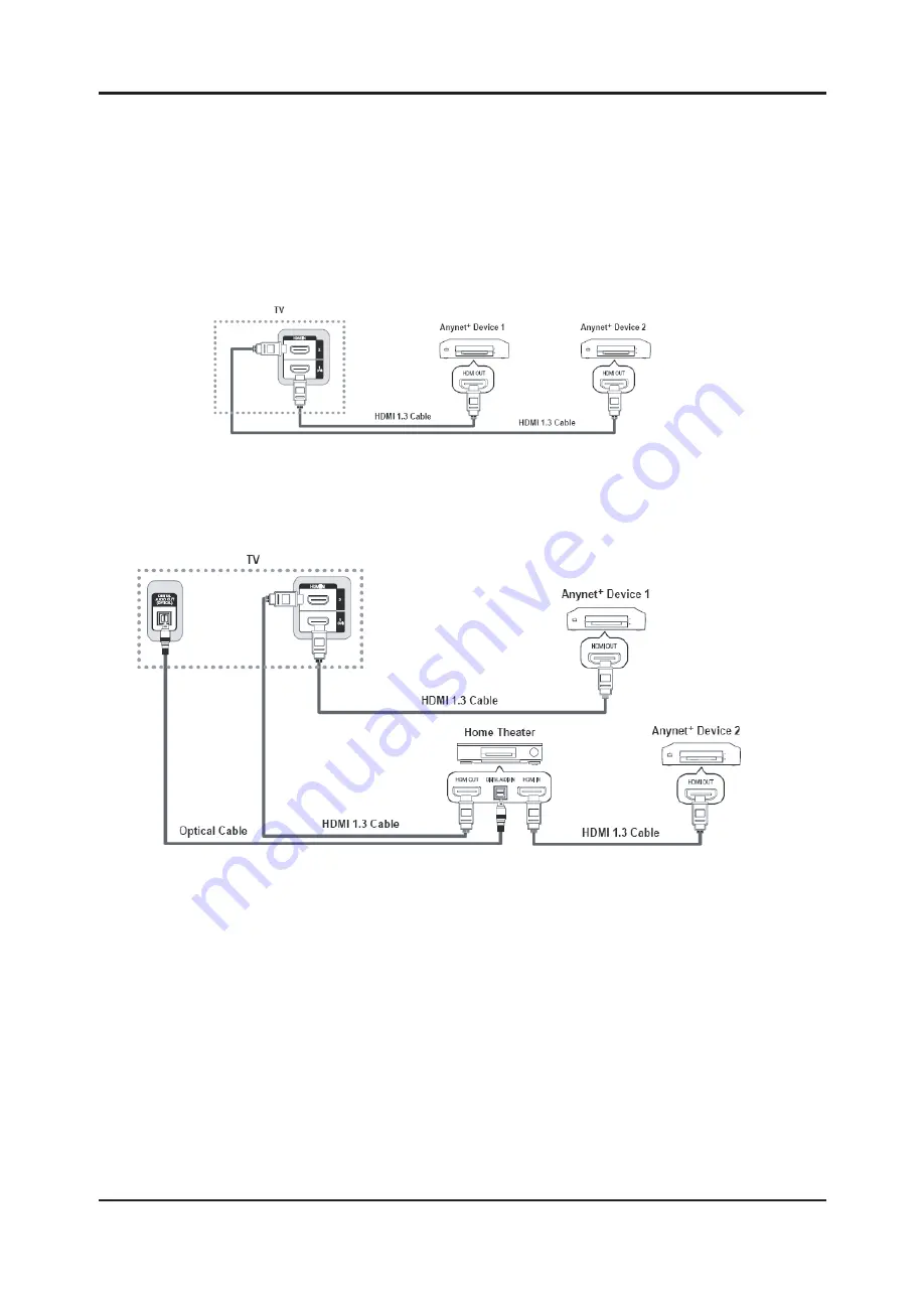
To connect to a TV
1. Connect the HDMI IN 1(DVI), 2 jack on the TV and the HDMI OUT jack of the corresponding device
using an HDMI cable.
To connect to Home Theater
1. Connect the HDMI IN 1(DVI), 2 jack on the TV and the HDMI OUT jack of the corresponding device
using an HDMI cable.
2. Connect the HDMI IN jack of the home theater and the HDMI OUT jack of the corresponding device
using an HDMI cable.
-
Connect the Optical cable between the DIGITAL AUDIO OUT (OPTICAL) jack on your TV and the Digital Audio
Input on the Home Theater.
-
When following the connection above, the Optical jack only outputs 2 channel audio. You will only hear sound
from the Home Theater’s Front Left and Right speakers and the subwoofer. If you want to hear 5.1 channel
audio, connect the DIGITAL AUDIO OUT (OPTICAL) jack on the DVD / Satellite Box (ie Anynet Device 1 or 2)
directly to the Amplifi er or Home Theater, not the TV.
-
Connect only one Home Theater.
-
You can connect an device using the HDMI 1.3 cable. Some HDMI cables may not support
functions.
-
works when the AV device supporting is in the Standby or On status.
-
supports up to 12 AV devices in total. Note that you can connect up to 3 devices of the same type.
Summary of Contents for UA32C5000QF
Page 19: ...Memo 1 4 1 Precautions...
Page 41: ...4 3 4 Troubleshooting 40 T Con F1 Pin 1 5...
Page 43: ...4 5 4 Troubleshooting...
Page 44: ...4 6 4 Troubleshooting WAVEFORMS 1 PC input V sink H sink R G B 2 LVDS output...
Page 46: ...4 8 4 Troubleshooting...
Page 47: ...4 9 4 Troubleshooting WAVEFORMS 3 HDMI input RX_Data RX_Clk 2 LVDS output...
Page 49: ...4 11 4 Troubleshooting...
Page 50: ...4 12 4 Troubleshooting WAVEFORMS 2 LVDS output...
Page 52: ...4 14 4 Troubleshooting...
Page 53: ...4 15 4 Troubleshooting WAVEFORMS 2 LVDS output...
Page 55: ...4 17 4 Troubleshooting...
Page 56: ...4 18 4 Troubleshooting WAVEFORMS 4 CVBS OUT Grey Bar 2 LVDS output...
Page 58: ...4 20 4 Troubleshooting...
Page 59: ...4 21 4 Troubleshooting WAVEFORMS 5 Compnent_Y Gray scale Pb Pr Color bar 2 LVDS output...
Page 61: ...4 23 4 Troubleshooting...
Page 62: ...4 24 4 Troubleshooting WAVEFORMS 7 Speaker out...
Page 76: ...4 38 4 Troubleshooting 4 8 PCB diagram 4 8 1 PCB layout...
Page 77: ...4 39 4 Troubleshooting 4 8 2 Main TOP 4 8 3 Main Inner 2...
Page 78: ...4 40 4 Troubleshooting 4 8 4 Main Inner 3 4 8 5 Main Bottom...
Page 79: ...4 41 4 Troubleshooting 4 8 6 Power_32 37 SMPS 4 8 7 Power_40 SMPS...


