background image

COLOR DOME CAMERA

User Guide

12

COLOR DOME CAMERA

User Guide

13

Installation

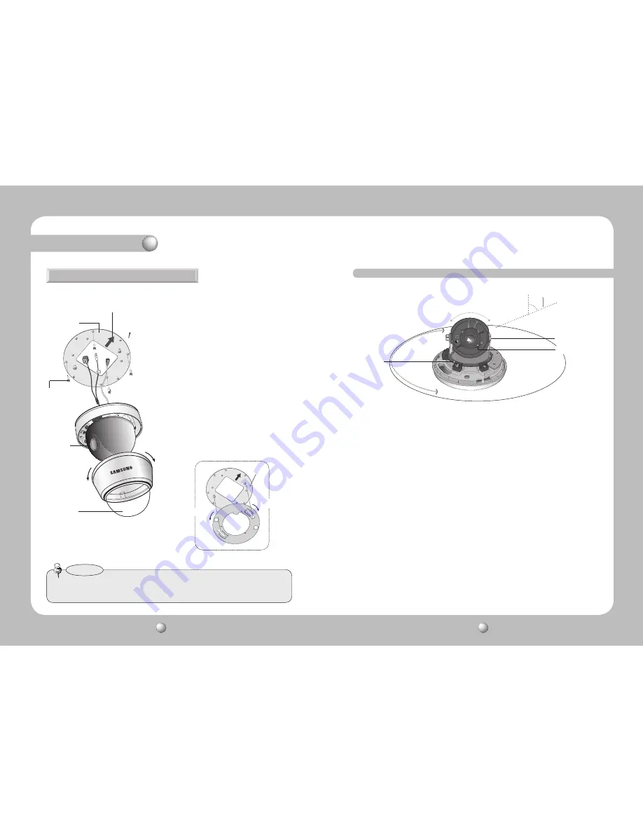
When installing on a adapter plate

1)  Place the bracket provided on the installation 

surface and fix it with the M4 tapping screws 

(provided). 

2)  When placing the camera body on the plate, 

insert the plate pin into the mounting hole on 

the body as shown in figure 2 and fix it by 

turning clockwise.

3)  When placing the camera body on the plate, 

make sure the camera cables pass through their 

respective designated holes.(When placing the 

cable through its side, thread it through the 

hole at the bottom.)

4)  After installation and adjustment of the camera 

are complete, secure the dome cover by turning 

it clockwise.

[Figure 2]

Locking direction

Plate pin

Unlocking direction

•  Please locate an arrow on bracket for installing direction that you wish to observe 

Area and then fix it with the M4 tapping screws.

Notes

Unlocking 

direction

M4 tapping  
screw (provided)

Dome cover

Adapter plate

An arrow for installing directions

CAMERA

Locking 
direction

Adjust the panning, tilting and rotate mechanism while checking the position on the monitor

1) You can adjust camera to any direction by using Pan, Tilt, Rotate mechanism.

  • Pan Bracket moves by 170° in each direction or 340° on the whole.
  • Tilt Body covers 73° in each direction or 146° in total. 
  •  The angle range of the Rotate Body is the same as that of the Pan Bracket. But one 

direction range is 195° and another is 145°

2) Methods of adjustment

  • 

The case of wall installation

1


After mounting the camera on a wall, adjusting the panning angle so that the camera can 
face the direction to monitor when tilted. 

2


Adjust the tilting angle by rotating the tilt base.

3


Loosen the rotate base hold screw and adjust rotate base for the best view. 

4


Tighten the rotate base hold screw. 

  • 

The case of ceiling installation 

1


After mounting the camera on a ceiling, adjusting the panning angle to the correct viewing 
position by rotating the pan base. 

2


Adjust the tilting angle by rotating the tilt base. 

3


Loosen the rotate base hold screw and adjust rotate base for the best view. 

4


Tighten the rotate base hold screw.

73˚

-170˚

145˚

195˚

170˚

Pan Base

Tilt Base

Rotate Base

Summary of Contents for SUD-2080F

Page 1: ...ENGLISH SuperHighResolutionUTPDomeCameraSUD 2080UserGuide Before installing and operating this product please read this manual thoroughly ...

Page 2: ...nstructions in the literature accompanying the appliance INFORMATION This equipment has been tested and found to comply with limits for a Class A digital device pursuant to part 15 of the FCC Rules These limits are designed to provide reasonable protection against harmful interference when the equipment is operated in a commercial environment This equipment generates uses and can radiate radio fre...

Page 3: ...ormanceW V DSP chip effectively removes low light gain noise and afterimage to provide clear images even in dark environments High Resolution By adopting a diagonal 6mm 1 3 410 000 NTSC pixel 470 000 PAL pixel SONY CCD the camera produces clear picture quality with a horizontal resolution of 600 TV lines in color and a horizontal resolution of 700 TV lines in B W mode SSDR Samsung Super Dynamic Ra...

Page 4: ...Therefore we can t compensate for material loss and or personalinjuriesbyrobbery fire naturaldisasterorothersuchevents Ignoring this information may result in material loss and or serious personal injuries including death Indicates Never Allowed Ignoring this information may result in material loss and or a slight injuries Indicates No Disassembling Warning Attention Special Mark Messages Precauti...

Page 5: ...spotlight or an object emitting strong light may cause smear or blooming Ensure that the power source complies with normal specifications before supplying it to the camera Notes Do not expose the camera to rain or other types of liquids May cause a product malfunction Wipe dry any liquids Liquids may contain minerals that are corrosive to electronic components Super High Resolution UTP Dome Camera...

Page 6: ...r Power input terminal If the UTP cable cannot be connected for power supply distance over 300m 1000ft for example this cable is used instead for connecting DC 12V AC 24V power to the camera Dome Cover Shield Case Overview 1 Separate the dome cover by rotating anti clockwise 2 Separate the shield case by pulling from the camera body The installation should be done by qualified service personnel or...

Page 7: ...irections CAMERA Locking direction Adjust the panning tilting and rotate mechanism while checking the position on the monitor 1 You can adjust camera to any direction by using Pan Tilt Rotate mechanism Pan Bracket moves by 170 in each direction or 340 on the whole Tilt Body covers 73 in each direction or 146 in total The angle range of the Rotate Body is the same as that of the Pan Bracket But one...

Page 8: ...cal lens zoom and focus 2 UTP Receiver Link Setup Additional Power input is needed SUD 2080 1Ch Passive Receiver DVR Monitor 225m 750ft or Less 1Ch Passive Receiver System Diagram 1 SUD 2080 4Ch Power Supply 4Ch Receiver DVR Monitor Controller The maximum power transmission distance for the camera is 300m 1000ft and the distance between the camera and the 4ch Receiver cannot exceed 900m 3000ft CH1...

Page 9: ...vironment condition the signal may become attenuated and distorted and cause the camera to function incorrectly even when the transmission distance is within the maximum If using RS 485 communication please use the SAMSUNG T SAMSUNG E PELCO D PELCO P BOSCH HONEYWELL VICON and PANASONIC Protocol If you are using the 1Ch Passive Receiver system setup please connect the adapter AC 24V or DC 12V direc...

Page 10: ... used and not copper coated steel as this will cause issues with the communication over the coaxial cable Notes CAMERA DVR CONTROLLER SET MENU ENTER OSD KEY UP UP KEY JOYSTICK UP DOWN DOWN KEY JOYSTICK DOWN LEFT LEFT KEY JOYSTICK LEFT RIGHT RIGHT KEY JOYSTICK RIGHT DVD DVR BNC RS 485 Installation Operating Your Camera MAIN SETUP LENS DC EXPOSURE BRIGHTNESS SHUTTER AGC SENS UP RETURN WHITE BAL ATW ...

Page 11: ...LENS LENS MAIN SETUP 1 LENS DC 2 EXPOSURE You can adjust the minimum shutter and maximum value of ESC shutter mode 2 The Lens mode has sub menu site as listed below BRIGHTNESS Adjusts the video brightness FOCUSADJ To adjust the DC lens focus correctly you must activate the Focus Settings mode To a Activate the Focus Settings mode adjust the lens focus and then deactivate the settings mode MAIN SET...

Page 12: ... and return to the SETUP menu Use theWhite Balance function to adjust the screen color 1 When the SETUP menu screen is displayed select White Bal by using the Function Setup switch so that the arrow indicates White Bal 2 Select a desired mode using the Function Setup switch White Bal White Balance MAIN SETUP 1 LENS DC 2 EXPOSURE 3 WHITE BAL ATW 4 SSDR OFF Select one of the following 5 modes as app...

Page 13: ...P menu screen is displayed select BACKLIGHT by using the Function Setup switch so that the arrow indicates BACKLIGHT 2 Select a desired mode using the Function Setup switch depending on the camera purpose MAIN SETUP 1 LENS DC 2 EXPOSURE 3 WHITE BAL ATW 4 SSDR OFF 5 BACKLIGHT OFF 6 SSNR3 ON OFF Not being used HLC High Light Compensation If the scene contains extremely bright light areas such as fro...

Page 14: ...uced OFF Deactivates SSNR3 Noise is not reduced 3 Set the SSNR3 mode to ON and press the Function Setup switch Then you can adjust the noise reduction level AUTO The mode is switched to Color in a normal environment but switches to B W mode when ambient illumination is low To set up the switching time forAUTO mode press the Function Setup switch You can turn on or off the burst signal on B W mode ...

Page 15: ...on or off the burst signal on B W mode SPECIAL 1 IMAGE ADJ 2 MONITOR LCD 3 CAM TITLE OFF 4 SYNC INT 5 MOTION DET OFF 6 PRIVACY OFF 7 COMM ADJ 8 LANGUAGE ENGLISH 9 RETURN 2 Select a desired mode using the Function Setup switch IMAGEADJ 1 When the SPECIAL menu screen is displayed select IMAGE ADJ by using the Function Setup switch so that the arrow indicates IMAGEADJ IMAGE SETUP 1 V REV OFF 2 H REV ...

Page 16: ...ction Setup switch Repeat this to enter multiple letters You can enter up to 15 letters CAMERA TITLE SETUP A B C D E F G H I J K L M N O P Q R S T U V W X Y Z a b c d e f g h i j k l m n o p q r s t u v w x y z 0 1 2 3 4 5 6 7 8 9 C L R P O S E N D FRONT DOOR 5 Enter a title move the cursor to POS and press the Function Setup switch The entered title appears on the screen Select the position to di...

Page 17: ...mera s identification number between 0 and 255 BAUD RATE You can select 2400 4800 9600 19200 38400 57600 bps UART MODE You can select NONE EVEN or ODD for the parity bits RET PKT Determines whether to send a command back to the controller device when a communication control command is sent to the camera DISP ID Display camera title on top left corner of the screen PROTOCOL Select the communication...

Page 18: ...an your lens with soft clean cloth Set the monitor to the proper condition If the camera is exposed to very strong light change the camera position The image on the screen is dark Adjust the contrast feature of the monitor If you have an intermediate device set the 75Ω Hi z properly The camera is not working properly and the surface of the camera is hot Check that you have properly connected the c...

Page 19: ...ish Korean Japanese Spanish French Portuguese Taiwanese PAL English Chinese German Italian French Spanish Russian Czech Polish Romanian Serbian Swedish Danish Turkish Portuguese SSDR ON OFF Level adjustable Backlight Compensation BLC HLC OFF Day Night COLOR BW AUTO ICR Gain Control LOW HIGH OFF White Balance ATW Outdoor Indoor Manual AWC 1 700 K 11 000 K SENS UP frame Integration AUTO OFF Selectab...

Page 20: ...opean Representative Address Equipment Type Environment CCTV Camera Model Name SUD 2080P Beginning Serial NO C5786V3Z200001X Year of Manufacture 2010 02 01 Conformance to EN 55022 2006 EN 50130 4 2003 We the undersigned hereby declare that the equipment specified above conforms to the above Directive s Manufacturer SAMSUNGTECHWIN CO LTD LegalRepresentativeinEurope Signature Signature Full Name BON...

Page 21: ...703 TEL 82 31 740 8151 8 FAX 82 31 740 8145 SAMSUNG TECHWIN EUROPE LTD Samsung House 1000 Hillswood Drive Hillswood Business Park Chertsey Surrey UNITED KINGDOM KT16 OPS TEL 44 1932 45 5300 FAX 44 1932 45 5325 SAMSUNG TECHWIN AMERICA Inc 1480 Charles Willard St Carson CA 90746 UNITED STATES Tol Free 1 877 213 1222 FAX 1 310 632 2195 www samsungcctvusa com SALES NETWORK ...

Reviews: