COLOR CCD CAMERA
COLOR CCD CAMERA
User’s Manual
User’s Manual
15
14
Connection
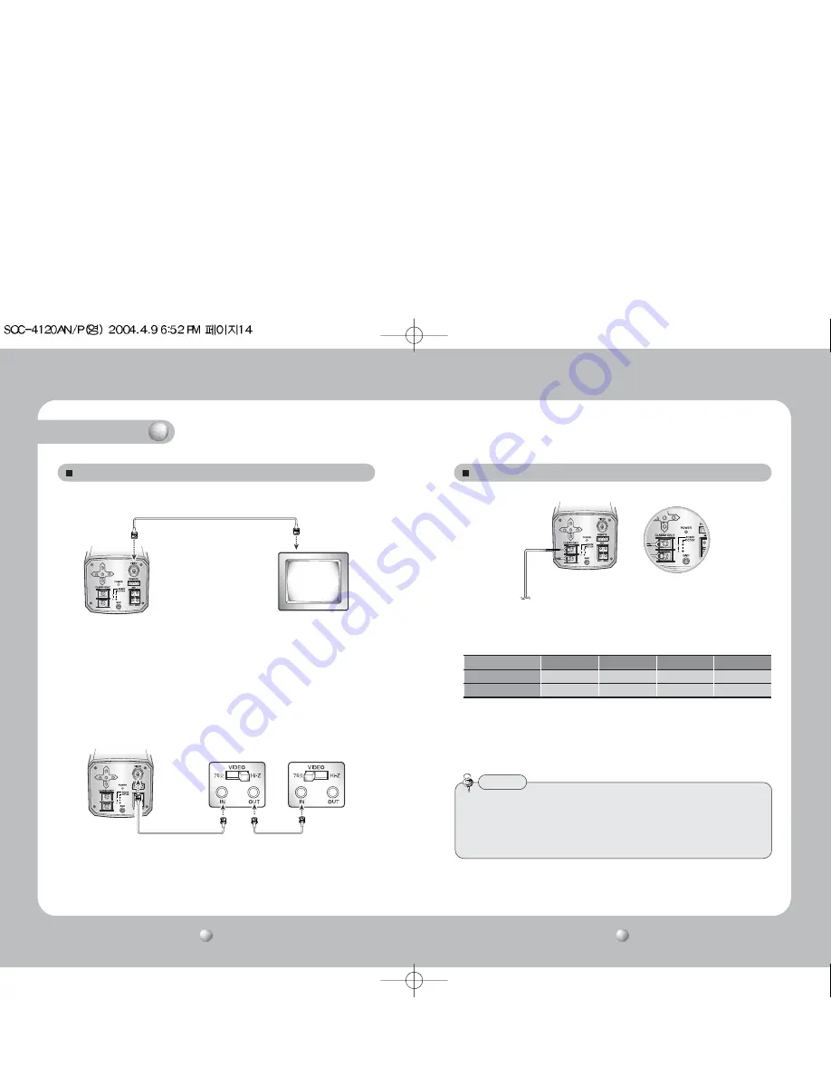
Connecting to Monitor
Connect the VIDEO Out jack to the monitor VIDEO In jack.
CCD Camera
Monitor
• As the connecting method varies with the instruments, refer to the manual
supplied with the instrument.
• If necessary, you can connect the monitor to the REMOTE jack on the back
of your camera. For details, see page 33.
• Only connect the cable when the power is turned off.
• Set the 75
Ω
/Hi-Z selection switch as shown below if you have an intermediate device.
CCD Camera
Intermediate
End monitor
Connecting to Power
• Use AC 24V/300mA or DC 12V/500mA power source for SOC-4120N/P.
Resistance of copper wire [at 20C˚ (68˚F)]
• As the voltage drop according to the length of the cable in the above table, a
camera may malfunction if there is an excessively long cable run.
* Voltage for camera operation: 12V DC ±10%
* Voltage drops in the above table are variable according to types of cable manufacturer.
Copper wire size (AWG)
#24(0.22mm
2
)
#22(0.33mm
2
)
#20(0.52mm
2
)
#18(0.83mm
2
)
Resistance (
Ω
/ m)
0.078
0.050
0.030
0.018
Voltage Drop (V/m)
0.028
0.018
0.011
0.006
• Be sure to connect power only after all the installation is complete.
• Note that AC or DC adaptor is not supplied with camera.
• Use the UL listed, class 2 power transformer of AC 24V adaptor.
• Ground should be connected to the GND terminal.
Notes
Summary of Contents for SOC-4120AN
Page 20: ...MEMO MEMO ...


