background image

8

Step-by-step installation guide

9

Step-by-step installation guide

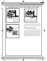
C.  DETERmINING WALL PLATE LOCATION UNDER YOUR CABINET

C

L

Plate position – beneath flat bottom cabinet.

CL

Plate position – beneath recessed bottom 

cabinet with front overhang

Draw a line on the
back wall equal to the 
depth of the front
overhang.

30" to Cooktop

Plate position – beneath recessed bottom cabinet with 

front overhang.

Your cabinets may have decorative trim that interferes 

with the microwave installation. Remove the decorative 

trim to install the microwave properly and to make it 

level.

THE mICROWAVE mUST BE LEVEL.

Use a level to make sure the cabinet bottom is level.

Draw a vertical line on the wall at the center of the 30˝ 

wide space. Draw a second, horizontal line on the wall 

below the cabinet to mark how far the inside of the 

front overhang descends below the cabinet. Tape the 

Rear Wall Template onto the wall so that the top of the 

template touches the bottom of the horizontal line and 

the centerline on the template lines up with the vertical 

line.

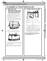
1. PLACEmENT OF THE mOUNTING PLATE

A.  REmOVING THE 

mICROWAVE OVEN FROm 

THE CARTON/REmOVING 

THE mOUNTING PLATE

1

.  Remove the installation instructions, Exhaust 

adaptor, filters, glass tray, and the small 

hardware bag. Do not remove the Styrofoam 

protecting the front of the oven.

2

.  Fold back all 4 carton flaps fully against carton 

sides. Then carefully roll the oven and carton 

over onto the top side. The oven should be 

resting in the Styrofoam.

Styrofoam

Carton

Carton

Styrofoam

3

.  Pull the carton up and off the oven.

4

.  Remove and properly discard plastic bags.

Screws

Screws

Mounting Plate

Screws

Mounting Plate

Screws

5

.  Remove the 2 screws from the mounting plate. 

This plate will be used as the rear wall template 

and for mounting.

NOTE

: You will have to reuse two screws in original 

loction of outcase after removing mounting plate.

B.  FINDING THE WALL STUDS

Wall Studs

Center

Center

Wall Studs

1

.  Find the studs using one of the following 

methods:


A.

  Stud finder–a magnetic device which locates 

nails.

OR


B.

  Use a hammer to tap lightly across the 

mounting surface to find a solid sound. This 

will indicate a stud location.

2

.  After locating the stud(s), find the stud’s center 

by probing the wall with a small nail to find the 

edges of the stud. Then, place a mark halfway 

between the edges. The center of any adjacent 

studs should be 16˝ or 24˝ from this mark.

3

.  Draw a line down the center of the studs.

THE mICROWAVE mUST BE CONNECTED TO 

AT LEAST ONE WALL STUD.

SMH1927_XAA_DE68-04108A-01_EN_120725.indd   8

2012-07-25   �� 7:54:31

Summary of Contents for SMH1927B/XAA

Page 1: ...hese instructions with the Consumer Note to Consumer Keep these instructions for future reference Skill level Installation of this appliance requires basic mechanical and electrical skills Proper installation is the responsibility of the installer Product failure due to improper installation is not covered under the Warranty READ CAREFULLY KEEP THESE INSTRUCTIONS This manual is made with 100 recyc...

Page 2: ...st the exhaust adaptor 12 B Recirculating non vented ductless 12 B1 Adapting the microwave blower for recirculation 12 B2 Installing the charcoal filter 13 C Outside back exhaust horizontal duct 14 C1 Adapting the microwave blower for outside back exhaust 14 3 Installation 15 A Preparing the rear wall for outside back exhaust 15 B Attach the mounting plate to the wall 15 C Use the top cabinet temp...

Page 3: ...efore use Insure proper ground exists before use The power cord of this appliance is equipped with a three prong grounding plug which mates with a standard three prong grounding wall receptacle to minimize the possibility of electric shock hazard from this appliance You should have the wall receptacle and circuit checked by a qualified electrician to make sure the receptacle is properly grounded I...

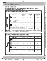
Page 4: ...ngth 41 ft IMPORTANT If a rectangular to round transition adaptor is used the bottom corners of the damper will have to be cut to fit using the tin snips in order to allow free movement of the damper OUTSIDE BACK EXHAUST EXAMPLE ONLY The following chart contains an example of one possible ductwork installation DUCT PIECES EQUIVALENT LENGTH x NUMBER USED EQUIVALENT LENGTH Wall Cap 40 ft x 1 40 ft 3...

Page 5: ...nt additional resistance to airflow and are equivalent to a section of straight duct which is longer than their actual physical size When calculating the total duct length add the equivalent lengths of all transitions and adaptors plus the length of all straight duct sections The chart below shows you how to calculate total equivalent ductwork length using the equivalent length in feet of some typ...

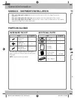
Page 6: ... INSTALLATION INSTRUCTIONS Wood Screws x 2 1 Template INSTALLATION INSTRUCTIONS Toggle Bolts and wing nuts 3 16 x 3 2 Template INSTALLATION INSTRUCTIONS Self aligning Machine Screws 28 x 3 2 You will find the installation hardware contained in a packet with the unit Check to make sure you have all these parts NOTE Some extra parts are included ADDITIONAL PARTS PART QUANTITY TOP CABINET TEMPLATE RE...

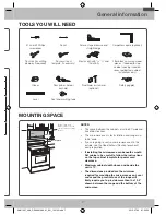
Page 7: ...S The space between the cabinets must be 30 wide and free of obstructions This microwave oven is for installation over ranges up to 36 wide If you are going to vent your microwave oven to the outside see the Hood Exhaust Section for exhaust duct preparation If installing the microwave oven beneath smooth flat cabinets be careful to follow the instructions on the top cabinet template for power cord...

Page 8: ...5 Remove the 2 screws from the mounting plate This plate will be used as the rear wall template and for mounting NOTE You will have to reuse two screws in original loction of outcase after removing mounting plate B Finding the wall studs Wall Studs Center Center Wall Studs 1 Find the studs using one of the following methods A Stud finder a magnetic device which locates nails OR B Use a hammer to t...

Page 9: ... a line on the back wall equal to the depth of the front overhang 30 to Cooktop Plate position beneath recessed bottom cabinet with front overhang 30 to Cooktop Draw a horizontal line to mark how far the inside of the front overhang descends below the cabinet Your cabinets may have decorative trim that interferes with the microwave installation Remove the decorative trim to install the microwave p...

Page 10: ... to avoid cutting fingers on sharp edges 1 Draw a Horizontal line on the wall at the bottom of the Rear Wall Template 2 Drill holes for toggle bolts in 3 locations Hole A Hole B Hole C as shown in the illustration above If the location of a hole lines up with a stud drill a 3 16 hole for a wood screw You cannot use a toggle bolt to attach the wall plate to a stud NOTE DO NOT MOUNT THE PLATE AT THI...

Page 11: ...haust adaptor is shipped assembled and attached to the filler upper Select the type of ventilation required for your installation and proceed to that section A Outside top exhaust vertical duct B Recirculating non vented ductless Adaptor in Place for Outside Top Exhaust Adaptor in Place for Outside Top Exhaust See page 12 See page 13 A Charcoal Filter Accessory Kit is required for the nonvented ex...

Page 12: ...the microwave you will need to open the top cabinet and adjust the exhaust adaptor so that you can connect it to the house duct For Front to Back Adjustment Slide the Exhaust Adaptor as Needed Blower Plate Back of Microwave Damper NOTE You must attach the house duct to the exhaust adaptor after installation is complete House Duct House Duct B Recirculating non vented ductless B1 Adapting the micro...

Page 13: ... of Microwave Before Roll After Roll Back of Microwave 5 Place the blower unit back into the opening CAUTION Do not pull or stretch the blower unit wiring Make sure the wires are not pinched 6 Secure the blower unit to the microwave with the screw B2 Installing the charcoal filter 1 Remove the screws on the top of the grill using a 1 Phillips screwdriver 2 Open the door 3 Remove the grill Push the...

Page 14: ...ter Rotation Back of Microwave Back of Microwave 6 Place the blower unit back into the opening AFTER Fan Blade Openings Facing Back End B End A CAUTION Do not pull or stretch the blower unit wiring Make sure the wires are not pinched NOTE The blower unit exhaust openings should match exhaust openings on the rear of microwave oven 7 Close the Blower Plate and attach the exhaust adaptor to the rear ...

Page 15: ...re Rear Wall horizontal duct only B Attach Mounting Plate to Wall C Prepare Top Cabinet D Mount the Microwave Oven E Connecting Ductwork vertical duct only A Preparing the rear wall for outside back exhaust You need to cut an opening in the rear wall for outside exhaust C L Read the instructions for outside back exhaust on the REAR WALL TEMPLATE Tape the REAR WALL TEMPLATE to the rear wall Cut the...

Page 16: ...ABINET TEMPLATE Tape it underneath the top cabinet Drill the holes following the instructions on the TOP CABINET TEMPLATE CAUTION Wear safety goggles when drilling holes in the cabinet bottom D Mount the microwave oven FOR EASIER INSTALLATION AND PERSONAL SAFETY WE RECOMMEND THAT TWO PEOPLE INSTALL THIS MICROWAVE OVEN IMPORTANT Do not grip or use the handle during installation NOTE If your cabinet...

Page 17: ...f Cabinet Recess Cabinet Bottom Shelf Equivalent to Depth of Cabinet Recess Cabinet Bottom Shelf Microwave Oven Top Cabinet Front Filler Block Self Aligning Screw 4 Attach the microwave oven to the top cabinet 5 Insert the 2 self aligning screws through the cabinet bottom shelf and filler block into the outer top cabinet of the unit Continue to support the unit until both screws are inserted and e...

Page 18: ...lace the house fuse or turn the breaker back on Insure proper ground exists before use 5 Plug the power cord into a dedicated 15 amp electrical outlet Insure proper ground exists before use Insure proper ground exists before use 6 Read the Owner s Manual 7 Keep installation instructions for the local inspector s use 4 Before you use your microwave SMH1927_XAA_DE68 04108A 01_EN_120725 indd 18 2012 ...

Page 19: ...19 Note SMH1927_XAA_DE68 04108A 01_EN_120725 indd 19 2012 07 25 7 54 37 ...

Page 20: ...Code No DE68 04108A 01 SMH1927_XAA_DE68 04108A 01_EN_120725 indd 20 2012 07 25 7 54 37 ...

Reviews: