


COLOR CCD CAMERA
User Guide
14
COLOR CCD CAMERA
User Guide
15
Installation Procedures
Before installing a lens, identify whether the lens to be installed is a C-Mount or CS-Mount.
This camera is set for a CS-Mount Lens by default. To install a C-Mount Lens, a
simple modification is required.
When Using C/CS Mount Lens
• Use the lens connector shown in the following figure. If the dimensions of the connector
are not correct, it may damage the camera, or the lens may not be installed firmly.
• If the lens is too heavy, the camera becomes unbalanced and
there may be problems. Use a lens that weighs less than
450g.
• When adjusting the Automatic Level Control (ALC) of an auto
iris lens, use Av mode if available. If you use the Pk mode, the
picture brightness may change continuously.
Notes
C-Mount Lens: 10mm or less
CS-Mount Lens: 5mm or less
• When Using a CS Mount Lens
Remove the protective glass cover at the
front of this product and turn the CS-Mount
Lens clockwise to install it. And set focus of
camera using Back Focus Control Lever of
camera side after combining CS-Mount lens.
• When Using a C Mount Lens
1. Remove the protective glass cover at the
front of this product and turn the C-Mount
Adapter clockwise to install it.
2. Turn the C-Mount lens clockwise to install
it.
3. Set focus of camera using Back Focus
Control Lever of camera side after
combining C-Mount lens.
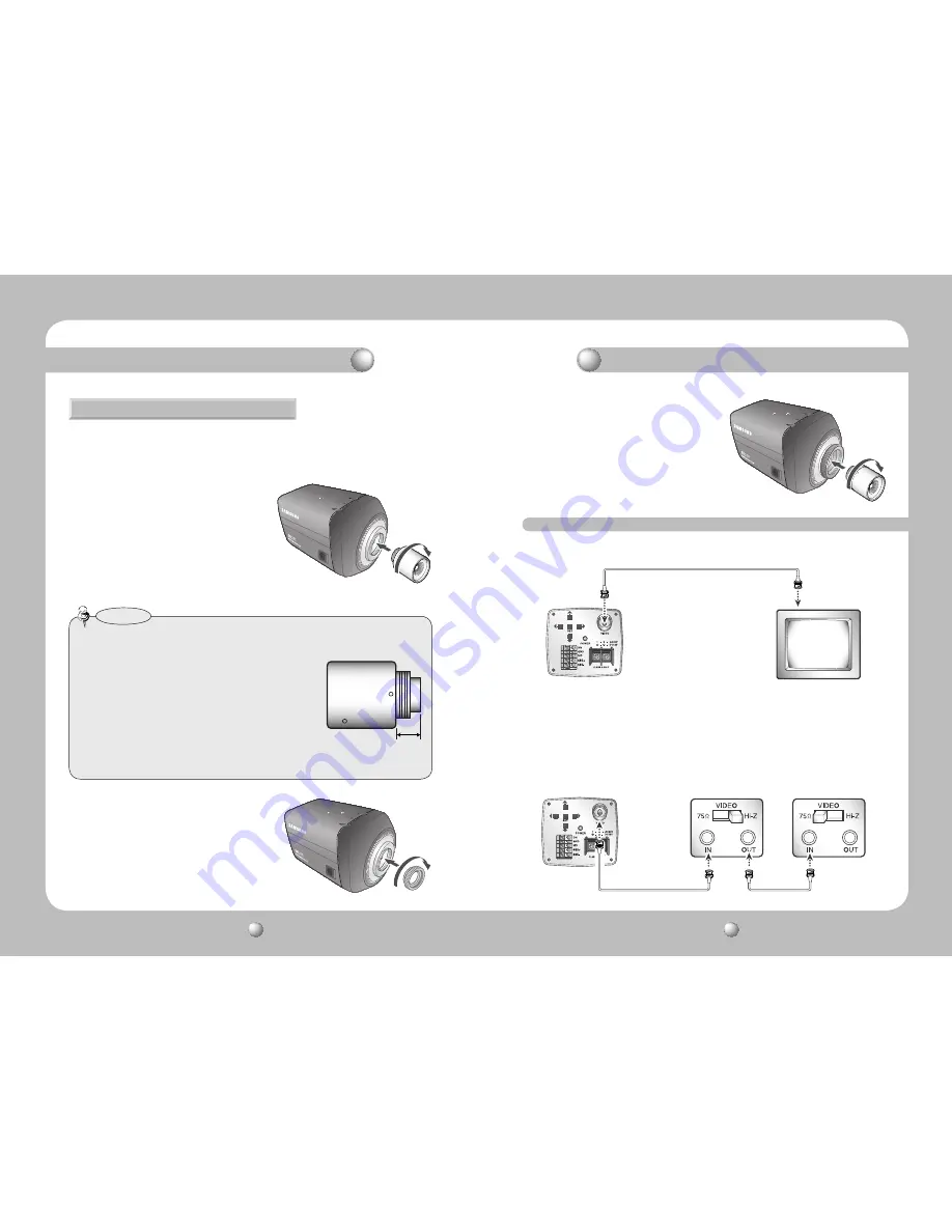
Installation Procedures
Connecting to Monitor
Connect the Video OUT port on the rear panel of the camera to a monitor.
• Since the connection procedure may differ depending on the type of monitor or
peripheral device to be connected, refer to the User Manual for the device to be
connected.
• Make sure to turn off the device to be connected before making any connections.
• Turn the 75
Ω
/Hi-Z switches of interim display devices to the Hi-Z position, and the
switches of any final device to the 75
Ω
position.
CCD Camera
CCD Camera
Intermediate
End monitor
Monitor
Summary of Contents for SHC-737 Series
Page 21: ......


