background image

36_ setup

setup

English_37


SETUP

USER

 :  Please use this menu item when using 

a monitor other than standard ones. 
You can change the gamma, PED 
level, and color gain in the sub menus.

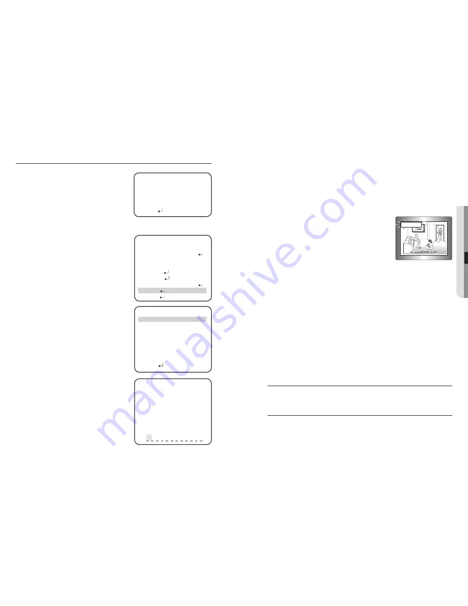
DISPLAY

 : Use this feature to designate a 

name for the camera, which will display on 
the monitor screen.

CAM TITLE

 :


If the camera is named, it is 
displayed on the monitor.

➊  

  Press the Function Setup switch to display the main 

setup menu and move the arrow indicator to ‘CAM 
TITLE’ using the Function Setup switch.

➋  

 Set ‘CAM TITLE’ to ‘ON’ using the Function Setup 
switch.

 If the CAM TITLE feature is set to ‘OFF’, the name 
will not displayed in the monitor

➌  

  Press the Function Setup switch.

➍  

 You can enter up to 15 characters.

a.  Move the cursor to the character entry fi eld 

using the Function Setup switch.

b.  Use the 4 direction of Function Setup Switch 

to select a desired character.

c.  Press the Function Setup switch to confi rm 

the selection of the blinking character. The 
character is then saved, and the cursor in the 
entry fi eld moves to the next position.

d.  Repeat steps 'a' through 'c' until the desired 

name has been entered.

-

y

-

M

USER MONITOR SETUP

GAMMA  

0.55

  PED LEVEL         


IIIIIIII

Â

IIIIIIIIIIIIIIIIIIIII 

17

 COLOR 

LEVEL 


IIIIIIIIIIIIIIIII

Â

IIIIIIIIIIII 

50

 RETURN   

      CAMERA TITLE SETUP

A B C D EF G H I J K L M
N O P Q R S T U V WXY Z
a b c d e f g h i  j k l m
n o p q r s t u v w x y z
- .     0 1 2 3 4 5 6 7 8 9


← →  

CLR


POS


END

Correcting Mistakes

 Move the cursor th ‘CLR’ and press the Function Setup switch to clear the entire entry. 
To modify one character, use LEFT or RIGHT to position the cursor above the character to be 
modifi ed and click the Function Setup switch after selecting the character to enter.

➎  

 Enter a title, move the cursor to ‘POS’ and press 
the Function Setup Switch. The entered title 
appears on the screen. Select the position to 
display the title on the screen by moving the 4 
direction of Function Setup Switch and press 
the Function Setup Switch. When the position is 
determined, select.

CAM ID

 : Displays camera ID on top left corner of the screen.

CAM INFO

 : Displays camera information on screen.

MOTION ALARM

 : You can toggle the use of the camera alarm.

ZOOM MAG

 :  Use th is feature to display the current zoom magnifi cation level on 

screen. Position the indicator over ‘ZOOM MAG’ using the Function 
Setup switch. Then set to ON using the Function Setup switch.

FONT COLOR

 : You can select the font color(white,yellow,green,red,blue)

LANGUAGE

 :  You can select the menu language according to your requirements.

• 

NTSC

 :  Korean, English, French, Spanish, Japanese, Portuguese, 

Taiwanese

• 

PAL

 :  English, French, German, Spanish, Italian, Chinese, Russian, Czech, 

Polish, Portuguese, Romanian, Serbian, Swedish, Danish, Turkish

END

 :  Select this to save the SPECIAL menu settings and return to the 

SPECIAL menu.

RESET

To reset your camera to factory default condition.

EXIT

To finish setup menu.

M

-

-

-

-

-

-

-

 FRONT DOOR

SPECIAL SETUP

#

  PRIVACY  

OFF 


DAY/NIGHT 

AUTO


DIS 

OFF


SYNC 

INT


COMM 

ADJ   


IMAGE 

ADJ   


MONITOR 

LCD   


 DISPLAY    


RETURN  

DISPLAY SETUP

CAM TITLE


OFF

 CAM 

ID


ON

 CAM 

INFO 


ON

 MOTION 

ALARM


OFF

 ZOOM 

MAG


ON

 FONT 

COLOR


WHITE

 LANGUAGE


ENGLISH

 RETURN 


Summary of Contents for SCO-2370

Page 1: ...High Resolution 37x Weatherproof Camera User Manual SCO 2370 ...

Page 2: ... time CAUTION RISK OF ELECTRIC SHOCK DO NOT OPEN CAUTION TO REDUCE THE RISK OF ELECTRIC SHOCK DO NOT REMOVE COVER OR BACK NO USER SERVICEABLE PARTS INSIDE REFER SERVICING TO QUALIFIED SERVICE PERSONNEL This symbol indicates that dangerous voltage consisting a risk of electric shock is present within this unit This symbol indicates that there are important operating and maintenance instructions in ...

Page 3: ...protection against harmful interference when the equipment is operated in a commercial environment This equipment generates uses and can radiate radio frequency energy and if not installed and used in accordance with the instruction manual may cause harmful interference to radio communications Operation of this equipment in a residential area is likely to cause harmful interference in which case t...

Page 4: ...ld with the apparatus When a cart is used use caution when moving the cart apparatus combination to avoid injury from tip over Unplug this apparatus during lightning storms or when unused for long periods of time When a cart is used use caution when moving the cart apparatus combination to avoid injury from tip over Refer all servicing to qualified service personnel Servicing is required when the ...

Page 5: ...er building eaves or places that are exposed to the dust and rain SSDR Samsung Super Dynamic Range For images with high contrast between bright and dark Areas from difficult lighting conditions such as backlighting this camera selectively illuminates darker Areas while retaining the same light level for brighter Areas to even out the overall brightness Communication RS 485 Coaxial communication me...

Page 6: ... Front cover Power input terminal Connect the power as specified for each model here MD Output Terminal Motion detection signals are output through this terminal RS 485 control terminal You can control SETUP MENU through this port by using external controllers like a Remote controller that RS 485 Communication is supported For details see page 15 Video output terminal Video signals are output thro...

Page 7: ...g to the below While the camera is powered the heater fan operates if its internal temperature drops below 10 C When the camera s internal temperature reaches 5 C the heater fan stops operating While the camera is powered and its internal temperature is between 50 C 15 C the message Low Temperature Wait appears When it reaches 15 C the camera is initialized and video begins output When the camera ...

Page 8: ...ower after installation y M Power Input Terminal RS 485 COMMUNICATION CONTROL Connecting to RS 485 Control Cable Using RS 485 communication will enable you to control the OSD menu from a SAMSUNG TECHWIN System Controller or DVR 1 Connection to a PC Connect the camera to the PC via a RS 485 converter using RS 485 and a serial cable EX SERIAL PORT OF THE PC COM1 p SERIAL CABLE p RS 485 CONVERTER p R...

Page 9: ...exceeds the recommended maximum please use an auxiliary video amp Distance Recommended Cable Specification 300m 3C2V RG 59 U 450m 5C2V RG 6 U 600m 7C2V RG 11 U If the camera is controlled through coaxial communication please use a video amp intended for coaxial communications Regular video amps do not transfer coaxial signals M setup MENU CONFIGURATION MAIN SETUP MENU SSDR OFF ON WHITE BAL ATW MAN...

Page 10: ... M MAIN SETUP 君SSDR ON WHITE BAL ATW BACKLIGHT OFF MOTION DET OFF FOCUS EXPOSURE SPECIAL RESET EXIT SSDR Samsung Super Dynamic Range SSDR illuminates darker spots of an image while retaining the same light level for brighter spots to even out the overall brightness of images with high contrast between bright and dark spots When the SETUP menu screen is displayed select SSDR by using the Function S...

Page 11: ...n Setup switch depending on the camera purpose OFF Not being used BLC Enables a user to directly select a desired area from a picture and to view the area more clearly HLC HIGH LIGHT COMPENSATION If the scene contains extremely bright light areas such as from car headlight the light can mask out much of the on screen detail LEVEL Adjust level of the HLC function LOW MIDDLE HIGH MASK TONE Change th...

Page 12: ...ut terminal and will zoom into a pre determined point When the SETUP menu screen is displayed select MOTION DETECTION by using the Function Setup switch so that the arrow indicates MOTION DETECTION OFF MOTION DETECTION mode is cancelled ON Any motion in the selected areas is observed AREA SEL You can select the area you wish to observe from the 8 area AREA MODE Determines whether to use the MD are...

Page 13: ...UTO Select AUTO and press the Function Setup switch to confirm Increase or decrease optical zoom ZOOM or digital zoom D ZOOM positions using the Function Setup switch while verifying the changes on screen Enabling D ZOOM ON means that digital zoom will activate once optical zoom ends The focus automatically adjusts when the lens zooms in and out ONE PUSH Focus is automatically adjusted just once a...

Page 14: ...The zoom postion is saved after 5 seconds when you set zoom function USER PRESET Preset user designated configurations using this feature Position the indicator over USER PRESET using the Function Setup switch and then set to ON using the Function Setup switch Press the Function Setup switch to confirm PRESET NO Up to 128 preset configuratons are supported PRESET SAVE Save configured preset PRESET...

Page 15: ...utter speed Position the indicator over SHUTTER using the Function Setup switch Then select the desired shutter mode A FLK ESC MANUAL using the Function Setup switch MANUAL Manual shutter speed setting A FLK NTSC 1 100 PAL 1 120 Flicker free mode ESC Automatic shutter speed setting optimal Auto operation is possible only when the IRIS is set to MANUAL Position the indicator over SHUTTER using the ...

Page 16: ...SENS UP LIMIT SETUP 䯝LIMIT X2 RETURN SPECIAL Press the Function Setup switch to access the main setup menu and then position the indicator over EXPOSURE using the Function Setup switch Press the Function Setup switch to confirm PRIVACY Hide an area you want to hide on the screen When the SPECIAL menu screen is displayed using the Function Setup switch so that the arrow indicates PRIVACY Set up the...

Page 17: ...talled environment y y y y y M AUTO SETUP 䯝DWELL TIME 5 SEC DURATION SLOW RETURN DIS The DIS mode can compensate for vibration of the camera When DIS is operating D ZOOM does not operate SYNC Two synchronization modes are available INTERNAL and EXTERNAL LINE LOCK In LINE LOCK mode it synchronizes the camera s video out signal to the external SYNC signal INT Internal synchronization LL External lin...

Page 18: ...e picture outline becomes stronger and clearer When the SHARPNESS level is too high video output may be unnatural or noisy Monitor Please change the settings value of video appropriate to your monitor LCD Please select this menu item when using an LCD monitor CRT Please select this menu item when using a CRT monitor M y IMAGE SETUP 䯝H REV OFF V REV OFF SHARPNESS ON RETURN LCD MONITOR SETUP 䯝GAMMA ...

Page 19: ...he Function Setup switch to clear the entire entry To modify one character use LEFT or RIGHT to position the cursor above the character to be modified and click the Function Setup switch after selecting the character to enter Enter a title move the cursor to POS and press the Function Setup Switch The entered title appears on the screen Select the position to display the title on the screen by mov...

Page 20: ...is not available f Make sure that the camera and monitor are installed within the recommended distance f Use the video amplifier equivalent to coaxitron if the recommended installation distance is exceeded SPECIFICATIONS SCO 2370N SCO 2370P POWER Input Voltage Dual AC 24V DC12V Power Consumption Max 3 8W 4 8W DC12V AC 24V Fan Heater Off Max 28W Heater Fan On AC 24V Video Imaging Device 1 4 Super H...

Page 21: ... Electronic Shutter Speed 1 60 1 1200 000 Digital Zoom On Off 2x 16x Flip Mirror On Off Communication RS 485 Coaxial Control Pelco Coaxitron Protocol Samsung T Samsung E Pelco D Pelco P AD Bosch Honeywell Vicon Panasonic ENVIRONMENTAL Operating Temperature Humidity 50 C to 50 C Less than 90 RH AC 24V 30 C to 50 C Less than 90 RH DC 12V Weather Proof IP68 MECHANICAL Dimension Ø114 x 378mm Weight 1 ...

Page 22: ...0Fh 00h 00h 00h 00h AFh CHECK SUM Focus Far Function Move focus lens to far direction Command Packet A0h CAM ID HOSTADDR 0100h 00h 00h 00h 00h AFh CHECK SUM Return Packet A0h CAM ID HOSTADDR 0100h 00h 00h 00h 00h AFh CHECK SUM Focus Near Function Move focus lens to near direction Command Packet A0h CAM ID HOSTADDR 0200h 00h 00h 00h 00h AFh CHECK SUM Return Packet A0h CAM ID HOSTADDR 0200h 00h 00h ...

Page 23: ...onditionally execute auto focus Command Packet A0h CAM ID HOSTADDR 0045h 00h 00h 00h 00h AFh CHECK SUM Return Packet A0h CAM ID HOSTADDR 0045h 00h 00h 00h 00h AFh CHECK SUM User Preset Save Function Save current user preset configuration information Command Packet A0h CAM ID HOSTADDR 0003h P1 00h 00h 00h Afh CHECK SUM Return Packet A0h CAM ID HOSTADDR 0003h P1 00h 00h 00h Afh CHECK SUM Parameter P1...

Page 24: ...Command Packet A0h CAM ID HOSTADDR 0010h 00h 00h 00h 00h AFh CHECK SUM Return Packet A0h CAM ID HOSTADDR 0010h 00h 00h 00h 00h AFh CHECK SUM OSD Menu Left Function Move OSD arrow to left Command Packet A0h CAM ID HOSTADDR 0004h 00h 00h 00h 00h AFh CHECK SUM Return Packet A0h CAM ID HOSTADDR 0004h 00h 00h 00h 00h AFh CHECK SUM OSD Menu Right Function Move OSD arrow to right Command Packet A0h CAM I...

Page 25: ...ipment Type Environment CCTV Camera Model Name SC0 2370P Beginning Serial NO C54N6V3Z300001X Year of Manufacture 2010 03 24 Conformance to EN 55022 2006 EN 50130 4 2003 We the undersigned hereby declare that the equipment specified above conforms to the above Directive s Manufacturer SAMSUNGTECHWIN CO LTD LegalRepresentativeinEurope Signature Signature Full Name BONJENG GU Full Name Position QUALI...

Page 26: ...MEMO MEMO ...

Page 27: ...MEMO MEMO ...

Page 28: ...MEMO MEMO ...

Page 29: ...463 400 TEL 82 70 7147 8740 60 FAX 82 31 8018 3745 SAMSUNG TECHWIN EUROPE LTD Samsung House 1000 Hillswood Drive Hillswood Business Park Chertsey Surrey UNITED KINGDOM KT16 OPS TEL 44 1932 45 5300 FAX 44 1932 45 5325 SAMSUNG TECHWIN AMERICA Inc 1480 Charles Willard St Carson CA 90746 UNITED STATES Tol Free 1 877 213 1222 FAX 1 310 632 2195 www samsungcctvusa com SALES NETWORK ...

Reviews: