41
TROUBLESHOOTING
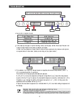
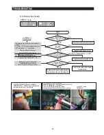
2) Manual defrost(fresh food compartment) function
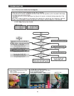
4-1-2. Display function of Communication error
2-1) If any key is pressed one more time during manual operation(fresh food compartment),
"rd" shows in the display and then manual operation will be canceled at once and fresh
food compartment will be defrosted.
2-2) At this moment, alarm beeps for 3 seconds(0.1 sec ON/ 1 sec OFF) during manual
defrost(fresh food compartment) function.
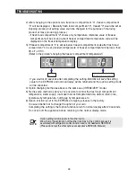
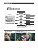
3) Simultaneous manual defrost(fresh food and freezer compartments) function
3-1) If any key is pressed one more time during manual defrost(defrost of fresh food
compartment, "rd"), "Fd" shows on the display and then fresh food and freezer
compartments defrost will operate.
Manual defrost of Fresh food and freezer compartments are followed by manual defrost
freezer compartment.
3-2) At this moment, alarm beeps for 3 seconds (0.5 sec ON/ 0.5 sec OFF) during manual
defrost function of fresh food and freezer compartment.
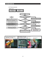
4-1) During defrosting of fresh food and freezer compartments simultaneously, if the display
panel change to the test mode and test button is pressed one more time, defrosting of
fresh food and freezer compartments will be canceled at the same time and will return
to the normal operation.
Or, all test functions will be canceled by turning main power ON again after it OFF.
1-1) If there is no answer for 10 seconds after the panel micom received the requirement of
communication, "Pc - Er" display on the panel PCB will be ON/OFF alternately until the
communication error is canceled. (0.5 sec ALL ON, 0.5 sec ALL OFF alternately)
4) Test cancel mode
(0.5 sec ALL ON, 0.5 sec ALL OFF alternately)
1) Display function when Panel
MAIN MICOM communication has error
Summary of Contents for RF265AARS RF266AARS RF26NBRS1RF265AABP RF266AABP RF26NBBP1RF265AAWP RF266AAWP RF26NBSH1RF265AASH...
Page 2: ......
Page 19: ...18 Refrigerator PRODUCT SPECIFICATIONS 2 9 Cooling Air Circulation Freezer ...
Page 120: ...119 8 1 Whole block diagram 8 Shematic Diagram AC115V AC115V AC115V 8 1 1 MODEL RF266 BETTER ...
Page 121: ...120 Shematic Diagram AC115V AC115V AC115V 8 1 2 MODEL RF265 GOOD RF26NB ...
Page 122: ...121 8 2 CIRCUIT DIAGRAM Shematic Diagram 8 2 1 Sheet 1 of 2 ...
Page 123: ...122 8 2 CIRCUIT DIAGRAM Shematic Diagram 8 2 2 Sheet 2 of 2 ...


