NO
Part
DISPLAY LED
Description
1
R-FAN HIGHEST
"a" and "b" at the lowest order digit of the R
compartment
In the case of the R-FAN HIGHEST operation, the corresponding LED is turned
on.
2
R-FAN HIGH
"a" at the lowest order digit of the R
compartment
In the case of the R-FAN HIGH operation, the corresponding LED is turned on.
3
R-FAN LOW
"b" at the lowest order digit of the R
compartment
In the case of the R-FAN LOW operation, the corresponding LED is turned on.
4
Overload
"e" at the lowest order digit of the R
compartment
If the external air temperature is 34
℃
or higher, the corresponding LED is turned
on.
5
Low Temperature
"f" at the lowest order digit of the R
compartment
If the external air temperature is 21
℃
or less, the corresponding LED is turned
on.
6
Demo Mode
"g" at the lowest order digit of the R
compartment
The LED is turned on in Demo Mode.
7
COMP
"a" at the lowest order digit of the F
compartment
In the case of the F COMP operation, the corresponding LED is turned on.
8
F-FAN HIGHEST
"b" and "c" at the lowest order digit of the F
compartment
In the case of the F-FAN HIGHEST operation, the corresponding LED is turned
on.
9
F-FAN HIGH
"b" at the lowest order digit of the F
compartment
In the case of the F-FAN HIGH operation, the corresponding LED is turned on.
10
F-FAN LOW
"c" at the lowest order digit of the F
compartment
In the case of the F-FAN LOW operation, the corresponding LED is turned on.
11
F compartment defrost heater
"d" at the lowest order digit of the F
compartment
The LED is turned on when the freezer defrosting heater operates.
12
C-FAN HIGHEST
"e" and "f" at the lowest order digit of the F
compartment
In the case of the C-FAN HIGHEST operation, the corresponding LED is turned
on.
13
C-FAN HIGH
"e" at the lowest order digit of the F
compartment
In the case of the C-FAN HIGH operation, the corresponding LED is turned on.
14
C-FAN LOW
"f" at the lowest order digit of the F
compartment
In the case of the C-FAN LOW operation, the corresponding LED is turned on.
15
F Valve
"b" at the second lowest order digit of the F
compartment
In the case of the F valve open, the LED is turned on.
16
CV Valve
"c" at the second lowest order digit of the F
compartment
If the CV valve opens, the LED is turned on.
17
R Valve
"f" at the second lowest order digit of the F
compartment
If the R valve opens, the LED is turned on.
18
French Heater
"g" at the second lowest order digit of the F
compartment
In the case of the French Heater operation, the corresponding LED is turned on.
19
CV-FAN HIGHEST
“Freezer” or “Thin Ice” for the CV
compartment
In the case of the CV-FAN HIGHEST operation, the corresponding LED is turned
on.
20
CV-FAN HIGH
“Freezer” for the CV compartment
In the case of the CV-FAN HIGH operation, the corresponding LED is turned on.
21
CV-FAN LOW
“Thin Ice” for the CV compartment
In the case of the CV-FAN LOW operation, the corresponding LED is turned on.
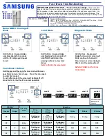
Hold buttons - Freezer, Fridge and Flex
Zone for 6 seconds. All on/off LED’s will
blink, Stop pressing to view load status.
Refer to next
Load Mode
22
CV compartment defrosting
heater
“Fridge” for the CV compartment
When the CV compartment defrosting heater operates,
the LED is turned on.
23
Normal
"e" and "f" in the lowest order digits of the R
compartment, and the LEDs are all turned off.
When the external temperature is within the range of
22
℃
~ 33
℃
.
24
Ice Room-FAN
"d" at the second lowest order digit of the F
compartment
When Ice Room-FAN operates, applicable LED ON.
25
Ice maker full
“e" at the second lowest order digit of the R
compartment
When the Ice Maker's Bucket is full, applicable LED ON
26
WiFi Status
Not connected to the IP sharer (AP) or the Internet: Off
Router(AP) connected: Blink
Internet connected: On


