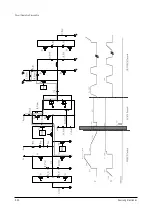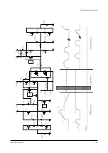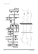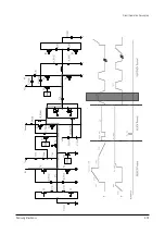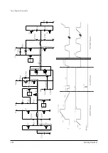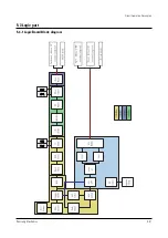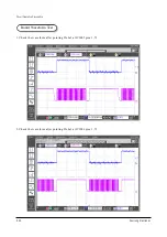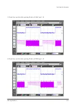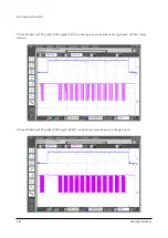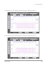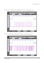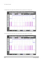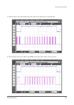
Circuit Operation Description
5-38
Samsung Electronics
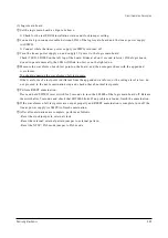
6) Using ASS'Y examination system
(1) Setting
!
Preadjust the output voltage to 5V when using the linear power supply.
Also, check if the output voltage is 5V when using SMPS.
@
Install the TEST PROM 256K, RST, F1, F2, and F3 on the logic main board.
To prevent misinsertion, make sure that the pin 1 of the PROM is inserted in the proper location
marked on the PCB.
#
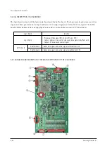
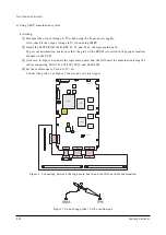
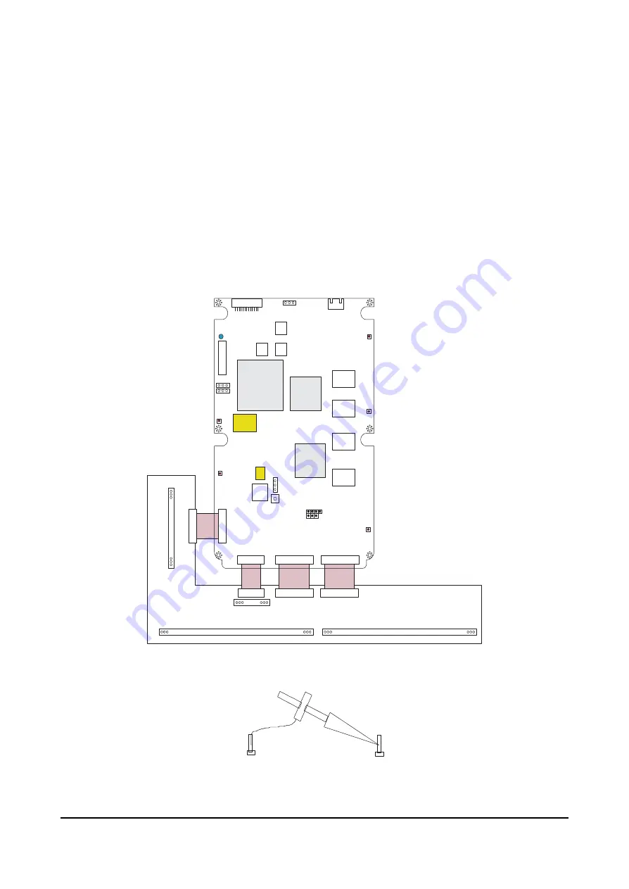
As shown in Figure 6, connect the logic main board and the JIG board for examination using the
cables connecting LX1(13P), LY1(30P), LE01, and LE02(80P).
$
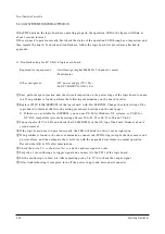
Set the oscilloscope to 5ms/div, 2V/div.
Connect the probe 1 as Figure 7 shows and set it to a trigger.
Figure 6. Connecting between the logic main board and the JIG board for examination
L
Y
1
LX1
LE01
LE02
30
1
1
13
1
80
1
80
L
Y
1
LX1
LE01
LE02
IC2011
IC2010
IC2002
IC2001
IC2012
IC2013
IC2003
256k
IC2017
RST
LD1
LA03
1
31
GND5
TP13
LD2001
CN01
F2
F1
F3
CN05
CN06
GND4
GND2
GND1
GND3
SW2001
CN02
Figure 7. Connecting probe 1 of the oscilloscope
TP13
GND5
Summary of Contents for PPM42S2X/XAA
Page 2: ...ELECTRONICS Samsung Electronics Co Ltd APR 2002 Printed in Korea AA82 ...
Page 10: ...3 2 Samsung Electronics MENO ...
Page 25: ...Circuit Operation Description Samsung Electronics 5 3 5 1 2 D PDP PS 42 BLOCK DIAGRAM ...
Page 38: ...Circuit Operation Description 5 16 Samsung Electronics 5 2 3 D DRIVER CIRCUIT DIAGRAM ...
Page 39: ...Circuit Operation Description Samsung Electronics 5 17 5 2 3 E DRIVER BOARD CONNECTOR LAYOUT ...
Page 40: ...Circuit Operation Description 5 18 Samsung Electronics ...
Page 41: ...Circuit Operation Description Samsung Electronics 5 19 ...
Page 42: ...Circuit Operation Description 5 20 Samsung Electronics ...
Page 43: ...Circuit Operation Description Samsung Electronics 5 21 ...
Page 44: ...Circuit Operation Description 5 22 Samsung Electronics ...
Page 45: ...Circuit Operation Description Samsung Electronics 5 23 ...
Page 46: ...Circuit Operation Description 5 24 Samsung Electronics ...
Page 47: ...Circuit Operation Description Samsung Electronics 5 25 ...
Page 48: ...Circuit Operation Description 5 26 Samsung Electronics ...
Page 49: ...Circuit Operation Description Samsung Electronics 5 27 ...
Page 50: ...Circuit Operation Description 5 28 Samsung Electronics ...
Page 51: ...Circuit Operation Description Samsung Electronics 5 29 ...
Page 52: ...Circuit Operation Description 5 30 Samsung Electronics ...
Page 82: ...Circuit Operation Description 5 60 Samsung Electronics ...
Page 83: ...Circuit Operation Description Samsung Electronics 5 61 ...
Page 84: ...Circuit Operation Description 5 62 Samsung Electronics MEMO ...
Page 93: ...Exploded View Parts List Samsung Electronics 7 1 7 Exploded View Parts List 7 1 PPM42S2X XAA ...
Page 106: ...Electrical Parts List 8 12 Samsung Electronics MEMO ...
Page 128: ...10 14 Samsung Electronics MEMO ...
Page 130: ...11 2 Samsung Electronics MENO ...
Page 133: ...Samsung Electronics Schematic Diagrams 12 3 TP01 12 3 SCALER3 3D COMB FILTER TP01 CVBS IN ...
Page 134: ...Schematic Diagrams 12 4 Samsung Electronics 12 4 SCALER4 VIDEO DECODER PIP FIRST IN OUTPUT ...
Page 135: ...Samsung Electronics Schematic Diagrams 12 5 12 5 SCALER5 VIDEO DA CON ...
Page 141: ...Samsung Electronics Schematic Diagrams 12 11 12 11 SOUND ...
Page 143: ...Samsung Electronics Schematic Diagrams 12 13 12 13 CONTROL REMOCON CONTROL REMOCON ...

