background image

8

Before connecting cables

OH85N


"

The color and shape of parts may differ from what is shown. Specifications are subject to change without notice to improve quality.

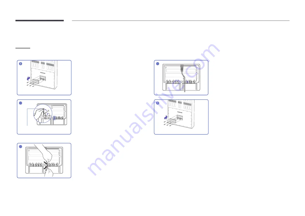
Unfasten the screws, then remove the cover.

4

The cable should be connected as shown.

2

Silicone bar

Remove the appropriate silicone bar for the thickness 

of the cable to connect. 
Different hole sizes and corresponding cable thickness 

for each:


"

7 Ø hole x 1: Insert the 7 Ø cable


"

5.5

 Ø hole x 6: Insert the 

5.5

 Ø cable


"

3 Ø hole x 2: Insert the 3 Ø cable


"

8.5

 Ø hole x 1: Insert the 

8.5

 Ø cable

Close the cover, then fasten the screws.


"

After all the cables are connected, make sure to 

close the cover and fasten the screws to ensure it 

is water tight.


"

Recommended torque: 10 - 12

 kgf.cm

3

Insert the appropriate cable into the hole from which 

the silicone bar was removed.

Summary of Contents for OH85N

Page 1: ...opyright forthis manual Use orreproduction of this manual in parts orentiretywithout the authorization of Samsung Electronics is prohibited Trademarks otherthan Samsung Electronics are property of theirrespective owners OH85N OH85N DK OH85N DJ The color and the appearance may differ depending on the product and the content in the manual is subject to change without prior notice to improve the perf...

Page 2: ...rts 5 OH85N 5 OH85N DK OH85N DJ 6 Before Installing the Product Installation Guide 7 Rotation 7 Ventilation 7 Before connecting cables 8 Power cable connection guide 11 Wall Mount Specifications 16 2 Specifications General 17 Preset Timing Modes 18 Appendix License 20 ...

Page 3: ...ppearance of the components may differfrom the images shown Checking the Components Quick Setup Guide Warranty card Not available in some locations Regulatory guide Batteries AAA x 2 Not available in some locations Remote Control Cover Cap x 16 Supported model OH85N Clamper x 6 Supported model OH85N DK OH85N DJ ...

Page 4: ...nction Using other display devices in the same space as the remote control of this product can cause the other display devices to be inadvertently controlled Use the remote control within 2 5 m to 4 m from the sensor on the product at an angle of 30 from the left and right Store used batteries out of reach of children and recycle Do not use a new and used battery together Replace both batteries at...

Page 5: ...nects to MDC using a LAN cable 10 100 Mbps Use Cat7 STP Type cable for the connection Shielded Twist Pair HDMI1 HDMI 2 Connects to a source device using a HDMI cable or HDMI DVI cable DP IN UHD 60Hz Connects to a PC using a DP cable Obtain sharp picture quality when viewing UHD content at 60Hz AUDIO OUT Outputs sound to an audio device via an audio cable RS232C IN Connects to MDC using an RS232C a...

Page 6: ... Use Cat7 STP Type cable for the connection Shielded Twist Pair 3 HDMI1 HDMI 2 Connects to a source device using a HDMI cable or HDMI DVI cable 4 DP IN UHD 60Hz Connects to a PC using a DP cable Obtain sharp picture quality when viewing UHD content at 60Hz 5 AUDIO OUT Outputs sound to an audio device via an audio cable 6 RS232C IN Connects to MDC using an RS232C adapter Noise filter Warning Do not...

Page 7: ...J are double sided display models When installing the product allow space of at least 200 mm from the ceiling and floor and keep the ambient temperature below 50 C Contact Samsung Customer Service Center for further details For outdoor products add a partition between the inlet and outlet to keep air paths separated Installation on a PerpendicularWall A Minimum 200 mm B Ambient temperature Under 5...

Page 8: ...ickness of the cable to connect Different hole sizes and corresponding cable thickness for each 7 Ø hole x 1 Insert the 7 Ø cable 5 5 Ø hole x 6 Insert the 5 5 Ø cable 3 Ø hole x 2 Insert the 3 Ø cable 8 5 Ø hole x 1 Insert the 8 5 Ø cable Close the cover then fasten the screws After all the cables are connected make sure to close the cover and fasten the screws to ensure it is water tight Recomme...

Page 9: ... cable into the hole from which the silicone barwas removed 2 Open the auxiliary display 6 Once all cables are connected place the cable staple back to the bottom of the main display 3 Remove the cable staple at the bottom of the main display Close the auxiliary display completely then fasten the brackets on both sides of the product 4 Silicone bar Remove the appropriate silicone bar for the thick...

Page 10: ...e cable into the hole from which the silicone barwas removed 2 Open the auxiliary display 6 Once all cables are connected place the bracket PCB back to the bottom of the main display 3 Remove the bracket PCB at the bottom of the main display Close the auxiliary display completely then fasten the brackets on both sides of the product 4 Silicone bar Remove the appropriate silicone bar for the thickn...

Page 11: ...switchboard Make sure that you have a 8 5 mm diameter waterproof power cable that can withstand 1800 W or higher The powercable must be connected to a 20 A orhigher amperage circuit 3 Put the soldered connected part of the power cables inside the product 2 Connect the two power cables to each other Solder and insulate the connected part 4 Close the rear cover and fasten the screws ...

Page 12: ...hould be connected to 40 A 20 A x 2 orhigheramperage circuits 4 Once all cables are connected place the cable staple back to the bottom of the main display 2 Connect the two power cables to each other Solder and insulate the connected part 5 Close the auxiliary display completely then fasten the brackets on both sides of the product 3 Put the soldered connected part of the power cables inside the ...

Page 13: ...hould be connected to 40 A 20 A x 2 orhigheramperage circuits 4 Once all cables are connected place the bracket PCB back to the bottom of the main display 2 Connect the two power cables to each other Solder and insulate the connected part 5 Close the auxiliary display completely then fasten the brackets on both sides of the product 3 Put the soldered connected part of the power cables inside the p...

Page 14: ...utral Live or Ground of each wire color of the external power cable may differ depending on the country Be sure to refer to the following table to correctly connect wires by the same meaning Neutral Live Ground Country BLUE BROWN GREEN YELLOW Others WHITE BLACK GREEN or GREEN YELLOW America BLUE BROWN GREEN YELLOW Europe BLACK RED GREEN YELLOW India WHITE BLACK GREEN or GREEN YELLOW Taiwan Japan ...

Page 15: ...Use the enclosed clampers to securely organize cables as shown in the below images Refer to the pin map to connect the AC power input and DC power output when using the products at inner space Connect 4 Fan cable at main board extended cable in order to cool off heat when using the product at inner space 1 3 Pin No 1 2 3 Spec LIVE NEUTRAL 1 11 Pin No 2 6 7 12 Spec 24 V GND ...

Page 16: ...ion Do not use a wall mount that can tilt Do not fasten the screws too firmly This may damage the product or cause the product to fall leading to personal injury Samsung is not liable for these kinds of accidents Do not keep the product turned on during the installation of the wall mount It may result in personal injury due to electric shock Do not use the guide holes forwall mounting Unit mm A 10...

Page 17: ...erature 4 F 122 F 20 C 50 C Humidity 5 95 non condensing Applicable before the product package is unpacked Plug and Play This monitor can be installed and used with any Plug and Play compatible systems Two way data exchange between the monitor and PC system optimizes the monitor settings Monitor installation takes place automatically However you can customize the installation settings if desired D...

Page 18: ...al Frequency 24 75 Hz HDMI 30 75 Hz DP Resolution Optimum resolution 3840 x 2160 60 Hz Maximum resolution 3840 x 2160 60 Hz Horizontal Frequency The time required to scan a single line from the left to the right side of the screen is called a horizontal cycle The reciprocal numberof a horizontal cycle is called horizontal frequency Horizontal frequency is measured in kHz Vertical Frequency The pro...

Page 19: ...7 861 72 809 31 500 VESA 640 x 480 37 500 75 000 31 500 VESA 800 x 600 37 879 60 317 40 000 VESA 800 x 600 48 077 72 188 50 000 VESA 800 x 600 46 875 75 000 49 500 VESA 1024 x 768 48 363 60 004 65 000 VESA 1024 x 768 56 476 70 069 75 000 VESA 1024 x 768 60 023 75 029 78 750 VESA 1152 x 864 67 500 75 000 108 000 VESA 1280 x 720 45 000 60 000 74 250 VESA 1280 x 800 49 702 59 810 83 500 VESA 1280 x 1...

Page 20: ...act the Samsung Customer center or send email to oss request samsung com THIS PRODUCT IS SOLD WITH A LIMITED LICENCE AND IS AUTHORISED TO BE USED ONLY IN CONNECTION WITH HEVC CONTENT THAT MEETS EACH OF THE THREE FOLLOWING QUALIFICATIONS 1 HEVC CONTENT ONLY FOR PERSONAL USE 2 HEVC CONTENT THAT IS NOT OFFERED FOR SALE AND 3 HEVC CONTENT THAT IS CREATED BY THE OWNER OF THE PRODUCT THIS PRODUCT MAY NO...

Reviews: