background image

66

Connecting and Using a Source Device

3

3 Connecting and Using a Source Device

3.2

Connecting and Using a PC

3.2.1

Connecting to a PC

z

Do not connect the power cable before connecting all other cables.

Ensure you connect a source device first before connecting the power cable.

z

Select a connection method suitable for your PC.


Connecting parts may differ in different products.


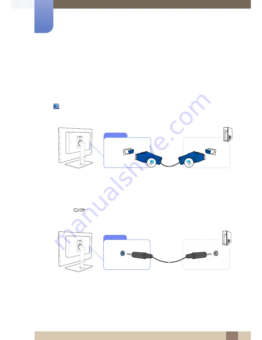
Connection Using the D-SUB Cable (Analogue Type)

1

Connect the D-SUB cable to the [RGB IN] port on the back of the product and the RGB port on the 

PC.

2

Connect the DC power adapter to the product and a power socket. Next, turn on the power switch 

on the PC.

(For details, refer to "2.2.7

 Connecting the Power".)

3

Press [

] to change the input source to 

Analog

.

Connecting a Stereo Cable

z

Connect the [AUDIO IN] port on the rear side of the monitor to the sound card of the PC.

RGB IN

AUDIO IN

Summary of Contents for NC241

Page 1: ...User manual NC191 NC241 The color and the appearance may differ depending on the product and the specifications are subject to change without prior notice to improve the performance BN46 00099C 02...

Page 2: ...icity and Safety 11 Installation and Safety 13 Operation and Safety 16 Correct posture to use the product PREPARATIONS 17 Checking the Contents 17 Removing the Packaging 18 Checking the Components 20...

Page 3: ...rial Driver 35 PCoIP 35 On Screen Display OSD 35 Connect Screen 36 OSD Options Menu 36 Configuration Window 46 Diagnostics Window 50 Information Window 52 User Settings Window 60 Password Window 62 Wa...

Page 4: ...ine CONFIGURING TINT 77 SAMSUNG MAGIC Color 77 Configuring SAMSUNG MAGIC Color 78 Red 78 Configuring Red 79 Green 79 Configuring Green 80 Blue 80 Configuring Blue 81 Color Tone 81 Configuring the Colo...

Page 5: ...D OTHERS 90 INFORMATION 90 Displaying INFORMATION 90 Configuring Volume in the Initial Screen INSTALLING THE SOFTWARE 91 Natural Color 91 What is Natural Color 92 MultiScreen 92 Installing the Softwar...

Page 6: ...ity for the Pay Service Cost to Customers 110 Not a product defect 110 A Product damage caused by customer s fault 110 Others 111 Correct Disposal 111 Correct Disposal of This Product Waste Electrical...

Page 7: ...n fee may be charged if either a an engineer is called out at your request and there is no defect in the product i e where you have failed to read this user manual b you bring the unit to a repair cen...

Page 8: ...le by the plug and do not touch the cable with wet hands Otherwise an electric shock may result 3 Wipe the monitor screen using a clean soft and dry cloth z Do not apply a cleaning agent that contains...

Page 9: ...e may cause fire and damage the product Be sure to allow the amount of space as shown below or greater when installing the product The exterior may differ depending on the product Precautions for stor...

Page 10: ...t hands z Otherwise an electric shock may result Insert the power plug all the way in so it is not loose z An unstable connection may cause a fire Ensure you connect the power plug to a grounded power...

Page 11: ...o completely cut the power to the product Power to the product cannot be completely cut off with the power button Hold the plug when disconnecting the power cord from the power socket z An electric sh...

Page 12: ...product to direct sunlight heat or a hot object such as a stove z Otherwise the product lifespan may be reduced or a fire may result Do not install the product within the reach of young children z The...

Page 13: ...tomer Service Center page 104 for repair Before moving the product turn off the power switch and disconnect the power cable and all other connected cables z Otherwise the power cord may be damaged and...

Page 14: ...esult Do not use or keep combustible spray or an inflammable substance near the product z An explosion or fire may result Ensure the vents are not blocked by tablecloths or curtains z Otherwise a fire...

Page 15: ...ric shock or electric leakage Use the product at the recommended resolution and frequency z Your eyesight may deteriorate Looking at the screen too close for an extended period of time can deteriorate...

Page 16: ...es z Sound particularly at a higher volume could potentially affect long term hearing Use the product in the correct posture as follows z Straighten your back z Allow a distance of 45 to 50cm between...

Page 17: ...hen you open the packaging with a sharp instrument 2 Remove the styrofoam from the product 3 Check the components and remove the styrofoam and plastic bag z The appearance of actual components may dif...

Page 18: ...ou purchased the product if any item is missing z The appearance of the components and items sold separately may differ from the image shown Components Components may vary depending on the country Qui...

Page 19: ...ations 1 1 Preparations Items sold separately The following items can be purchased at your nearest retailer LAN cable D SUB cable USB cable RS232C cable Stereo cable DVI cable USB mouse Keyboard Headp...

Page 20: ...aintain the current settings or lock the OSD control to prevent unintended changes to settings Enable To lock the OSD control press the MENU button for five seconds Disable To unlock the locked OSD co...

Page 21: ...or off the product z Go to SETUP RESET Power Key and select Power Off or Screen Off Refer to 7 5 Power Key for details on Power Key z To turn the product on or off when Power Off is selected press the...

Page 22: ...utput device such as headphones Connect to a microphone Connect to an audio input source using an audio cable Connect to a USB device Connect to a PC using the D SUB cable Connect to a secondary monit...

Page 23: ...23 Preparations 1 1 Preparations Connect to the power cable Speakers If the 11th digit of the model code is M the model has internal speakers E g LF19NEBHBNM LF24NEBHBNM Port Description ON POWER IN...

Page 24: ...shion on a flat surface Next place the product with the face down on top of the cloth or cushion Insert the stand base into the stand in the direction of the arrow Do not remove the fixing pin until y...

Page 25: ...z The monitor tilt and height can be adjusted z Hold the top center of the product and adjust the height carefully 1 3 3 Rotating the Monitor You can rotate your monitor as shown below z Be sure to fu...

Page 26: ...on the product with the corresponding parts on the wall mount kit or desktop stand you want to attach Place a protective cloth or cushion on a flat surface Next place the product with the face down o...

Page 27: ...wall ensure you purchase a wall mount kit that can be installed 10cm or farther away from the wall z Be sure to use a wall mount kit that complies with the standards z To install the monitor using a...

Page 28: ...uality graphic work z This monitor enables reinforced security because it is used by connecting it to a server PC and enabling you to access the Internet create documents and edit figures In addition...

Page 29: ...N cable to LAN on the back of the product z It is not supported when the network speed is below or equal to 10Mbps z Use Cat7 STP Type cable for the connection STP Shielded Twist Pair 2 2 2 Connecting...

Page 30: ...duct 2 2 4 Connecting to Headphones or Speakers 1 Connect an audio output device such as headphones or speakers to at the back of the product 2 2 5 Connecting a SERIAL cable 1 Using the RS 232C cable...

Page 31: ...ct to a dual monitor z Connect to the DVI OUT port to display the same picture on another monitor such as the projector For presentation purposes z The maximum resolution is 1920 x 1200 when a dual mo...

Page 32: ...storage device DSC MP3 external storage etc Connecting one Host PC to many client device is possible only when virtualization solution like vmware is installed in Host PC Host PC HUB LAN Cable Monito...

Page 33: ...o Serial Driver Install the driver on the server PC 1 Insert the driver installation CD ROM into the CD ROM drive 2 Click on USB SERIAL Driver 3 Click Next 4 In the License Agreement window select I a...

Page 34: ...IP 2 2 Using PCoIP 5 Specify the Destination folder path to install the program and click Install If the directory path is not specified the program will be installed in the default directory path 6 C...

Page 35: ...lick the Options menu on the Connect window 2 4 2 Connect Screen The Connect window will appear during startup except when the client is configured for a managed startup or auto reconnect You can chan...

Page 36: ...Topology as well as the PCoIP protocol image quality z Password This option lets you update the administrative password for the device This option is available through the Management Console program V...

Page 37: ...ured using the Administrative Web Interface Figure 2 3 Network Configuration z Enable DHCP When Enable DHCP is enabled the device will contact a DHCP server to be assigned an IP address subnet mask ga...

Page 38: ...s field is read only on this page z Ethernet Mode Lets you configure the Ethernet mode of the host or client as Auto 100 Mbps Full Duplex 10 Mbps Full Duplex When you choose 10 Mbps Full Duplex or 100...

Page 39: ...n Protocol version 6 DHCPv6 for your device z Primary DNS The primary DNS IP address of the device If DHCPv6 is enabled this field is automatically populated by the DHCPv6 server z Secondary DNS The s...

Page 40: ...dministrative Web Interface Figure 2 5 Label Configuration z PCoIP Device Name If the PCoIP Device Name allows the administrator to give the Host or Portal a logical name The default value is pcoip ho...

Page 41: ...rward multicast traffic between subnets DNS SRV Discovery is the recommended discovery mechanism because most deployments do not allow this Figure 2 6 Discovery Configuration z Enable Discovery If the...

Page 42: ...strative Web Interface Figure 2 7 Session Configuration z Connection Type When you select a direct session connection type from the Session page specific configuration options will appear Figure 2 8 C...

Page 43: ...anguage for OSD only It does not affect the language setting for the actual user session Supported languages English French German Greek Spanish Italian Portuguese Korean Japanese Traditional Chinese...

Page 44: ...you enable the Extended Display Identification Data EDID override mode This function is only available through the OSD Under normal operation the GPU in the host computer queries a monitor attached to...

Page 45: ...Windows prior to Windows 7 once the host had no EDID information it would assume no monitors were attached and would never recheck This option ensures that the host always has EDID information when t...

Page 46: ...ers When you click this button a message will appear prompting you for confirmation This prevents an accidental reset 2 4 5 Diagnostics Window The Diagnostic menu contains links to pages with run time...

Page 47: ...lso be initiated using the administrative web interface Figure 2 13 Event Log z View event log message The View event log messages field displays log messages with time stamp information There are two...

Page 48: ...z Bytes Statistics Bytes Sent The total number of bytes sent in the current last session Bytes Received The total number of bytes received in the current last session z Round Trip Latency The minimum...

Page 49: ...49 Using PCoIP 2 2 Using PCoIP Figure 2 15 PCoIP Processor...

Page 50: ...igure 2 16 Ping z Ping Settings Destination IP Address or FQDN to ping Interval Interval between ping packets Packet Size Size of the ping packet z Packets Sent Number of ping packets transmitted Rece...

Page 51: ...erial number Firmware Part Number Part number of the current firmware Hardware Version Host client hardware version number z Firmware Information The Firmware Information reflects the current PCoIP fi...

Page 52: ...sion code of the current bootloader Bootloader Build Date Build date of the current bootloader 2 4 7 User Settings Window The User Settings page allows you to access tabs to define the Certificate Che...

Page 53: ...ative web interface Figure 2 18 VMware View Configuration z Reject the unverifiable connection Configure the client to reject the connection if a trusted and valid certificate is not installed z Warn...

Page 54: ...oard Host Driver function is being used Refer to the PCoIP Host Software for Windows User Guide TER0810001 for more details This function is only available through the OSD It is not available in the A...

Page 55: ...1 for more details This setting is only available through the OSD It does not appear on the Administration Web Interface z You can also configure the keyboard repeat settings through the PCoIP host so...

Page 56: ...ient WAN Network Guidelines for more details The Image parameters can also be configured using the Administrative Web Interface Figure 2 21 Image z Image Quality Preference Use the slider to adjust th...

Page 57: ...n a host card and a zero client refer to the PCoIP Host Software for Windows User Guide TER0810001 Always change the Display Topology settings using the Display Topology tab on the zero client OSD Opt...

Page 58: ...ate a PCoIP session and the display that is requested for the Windows taskbar after you initiate the session Port 1 Select to configure DVI 1 port on the zero client as the primary port Port 2 Select...

Page 59: ...supported z Right click delay Slide the pointer to a position between Long and Short to determine how long a user must touch and hold the screen to emulate a right click z Touch screen calibration Whe...

Page 60: ...d This field must match the current administrative password before you can update the password z New Password The new administrative password for both the administrative web interface and the local OS...

Page 61: ...PCoIP 2 2 Using PCoIP Figure 2 25 Authorized Password Reset Details on how to use PCoIP are subject to change without notice To view the latest information visit the Teradici website at http www tera...

Page 62: ...connected to ensure the feature works when the product is turned off z The feature is intended to power on the product It does not support the function to power off the product Configuring the setting...

Page 63: ...s detected Changes include clicking a mouse button or pressing a key on the keyboard Configuring the settings 1 Set the product and PC IP addresses to enable the product to connect to the PC over a ne...

Page 64: ...product to connect to the PC over a network 2 Enter the IP address set for the product in the URL address field on the PC to access the product administrative web page 3 Log in Log In and select Uplo...

Page 65: ...ng a source device read the user manual provided with it The number and locations of ports on source devices may differ from device to device z Do not connect the power cable until all connections are...

Page 66: ...PC Connecting parts may differ in different products Connection Using the D SUB Cable Analogue Type 1 Connect the D SUB cable to the RGB IN port on the back of the product and the RGB port on the PC 2...

Page 67: ...allation driver is contained on the CD supplied with the product 1 Insert the user manual CD provided with the product into the CD ROM drive 2 Click Windows Driver 3 Follow the instructions given on t...

Page 68: ...press 2 To hide the information message press z If the optimum resolution is not selected the message will appear up to three times for a specified time even when the product is turned off and on aga...

Page 69: ...Panel on your PC to obtain optimum picture quality z The picture quality of TFT LCDs may degrade if the optimum resolution is not selected Changing the Resolution on Windows XP Go to Control Panel Dis...

Page 70: ...70 Connecting and Using a Source Device 3 3 Connecting and Using a Source Device Changing the Resolution on Windows 7 Go to Control Panel Display Screen Resolution and change the resolution 1 2 3 4...

Page 71: ...is set to Dynamic Contrast mode 4 1 1 Configuring Brightness 1 Press any button on the front of the product to display the OSD guide Next press to display the corresponding menu screen 2 Press to move...

Page 72: ...le when Color is in Full or Intelligent mode 4 2 1 Configuring Contrast 1 Press any button on the front of the product to display the OSD guide Next press to display the corresponding menu screen 2 Pr...

Page 73: ...is in Full or Intelligent mode 4 3 1 Configuring Sharpness 1 Press any button on the front of the product to display the OSD guide Next press to display the corresponding menu screen 2 Press to move t...

Page 74: ...screen will appear z Custom Customize the contrast and brightness as required z Standard Obtain a picture quality suitable for editing documents or using Internet z Game Obtain a picture quality suit...

Page 75: ...front of the product to display the OSD guide Next press to display the corresponding menu screen 2 Press to move to Picture and press on the product 3 Press to move to Coarse and press on the product...

Page 76: ...on on the front of the product to display the OSD guide Next press to display the corresponding menu screen 2 Press to move to Picture and press on the product 3 Press to move to Fine and press on the...

Page 77: ...isplay the corresponding menu screen 2 Press to move to COLOR and press on the product 3 Press to move to Color and press on the product The following screen will appear z Off Disable Color z Demo Com...

Page 78: ...ent mode 5 2 1 Configuring Red 1 Press any button on the front of the product to display the OSD guide Next press to display the corresponding menu screen 2 Press to move to COLOR and press on the pro...

Page 79: ...nt mode 5 3 1 Configuring Green 1 Press any button on the front of the product to display the OSD guide Next press to display the corresponding menu screen 2 Press to move to COLOR and press on the pr...

Page 80: ...ent mode 5 4 1 Configuring Blue 1 Press any button on the front of the product to display the OSD guide Next press to display the corresponding menu screen 2 Press to move to COLOR and press on the pr...

Page 81: ...r Tone and press on the product The following screen will appear z Cool 2 Set the color temperature to be cooler than Cool 1 z Cool 1 Set the color temperature to be cooler than Normal mode z Normal D...

Page 82: ...he OSD guide Next press to display the corresponding menu screen 2 Press to move to COLOR and press on the product 3 Press to move to Gamma and press on the product The following screen will appear 4...

Page 83: ...tton on the front of the product to display the OSD guide Next press to display the corresponding menu screen 2 Press to move to SIZE POSITION and press on the product 3 Press to move to H Position or...

Page 84: ...he front of the product to display the OSD guide Next press to display the corresponding menu screen 2 Press to move to SIZE POSITION and press on the product 3 Press to move to Menu H Position or Men...

Page 85: ...y the OSD guide Next press to display the corresponding menu screen 2 Press to move to SETUP RESET and press on the product 3 Press to move to Reset and press on the product The following screen will...

Page 86: ...he product to display the OSD guide Next press to display the corresponding menu screen 2 Press to move to SETUP RESET and press on the product 3 Press to move to Language and press on the product The...

Page 87: ...1 Press any button on the front of the product to display the OSD guide Next press to display the corresponding menu screen 2 Press to move to SETUP RESET and press on the product 3 Press to move to D...

Page 88: ...t press to display the corresponding menu screen 2 Press to move to SETUP RESET and press on the product 3 Press to move to Menu Transparency and press on the product The following screen will appear...

Page 89: ...ff the screen Press the power button A message appears The screen will turn off in 5 seconds Power Off Press hold for 2 seconds After 5 seconds the screen switches off The power indicator on the front...

Page 90: ...ut source frequency and resolution will appear The displayed menu items may vary depending on the model 8 2 Configuring Volume in the Initial Screen Adjust the Volume by pressing the button when the O...

Page 91: ...olor is a color management system developed by Samsung Electronics to resolve this problem This software works with Samsung products only and enables you to adjust the displayed colors on the screen t...

Page 92: ...k the MultiScreen setup file on the CD ROM 3 When the Installation Wizard appears click Next 4 Follow the instructions given on the screen to proceed with installation z The software may not work prop...

Page 93: ...At least 32MB of memory z At least 60MB of free space on the hard disk drive 9 2 2 Removing the Software Click Start select Settings Control Panel and then double click Add or Remove Programs Select...

Page 94: ...uct is working normally If the screen remains blank check the PC system video controller and cable 10 1 2 Checking the Resolution and Frequency For a mode that exceeds the supported resolution refer t...

Page 95: ...of resolution and frequency compatible with the product Next if required change the settings referring to Standard Signal Mode Table page 101 in this manual and the INFORMATION menu on the product Th...

Page 96: ...onitor settings z Windows ME 2000 Go to Control Panel Display Settings Advanced Monitor and adjust Refresh rate under Monitor settings z Windows Vista Go to Control Panel Appearance and Personalizatio...

Page 97: ...indows 7 Go to Control Panel Appearance and Personalization Display Adjust Resolution and adjust the resolution How do I set power saving mode z Windows XP Set power saving mode in Control Panel Appea...

Page 98: ...AN Port Power Supply This product uses 100 to 240V Refer to the label at the back of the product as the standard voltage can vary in different countries Signal connectors RGB IN DVI OUT Speakers 1 W x...

Page 99: ...lly However you can customize the installation settings if desired Panel Dots Pixels Due to the nature of the manufacturing of this product approximately 1 pixel per million 1ppm may be brighter or da...

Page 100: ...The power consumption level can vary in different operating conditions or when settings are changed z To reduce the power consumption to 0 watts turn off the power switch on the back of the product or...

Page 101: ...adjusted If the signal transmitted from the PC does not belong to the standard signal modes the screen may be blank even though the power LED turns on In such a case change the settings according to...

Page 102: ...31 500 VESA 800 x 600 35 156 56 250 36 000 VESA 800 x 600 37 879 60 317 40 000 VESA 800 x 600 48 077 72 188 50 000 VESA 800 x 600 46 875 75 000 49 500 MAC 832 x 624 49 726 74 551 57 284 VESA 1024 x 7...

Page 103: ...horizontal frequency Horizontal frequency is measured in kHz z Vertical Frequency Repeating the same picture dozens of times per second allows you to view natural pictures The repeat frequency is cal...

Page 104: ...http www samsung com BOLIVIA 800 10 7260 http www samsung com BRAZIL 0800 124 421 4004 0000 http www samsung com CHILE 800 SAMSUNG 726 7864 From mobile 02 482 82 00 http www samsung com COLOMBIA 01 80...

Page 105: ...com latin_en English PERU 0 800 777 08 http www samsung com PUERTO RICO 1 800 682 3180 http www samsung com TRINIDAD TOBAGO 1 800 SAMSUNG 726 7864 http www samsung com VENEZUELA 0 800 100 5303 http ww...

Page 106: ...http www samsung com LATVIA 8000 7267 http www samsung com LITHUANIA 8 800 77777 http www samsung com LUXEMBURG 261 03 710 http www samsung com MACEDONIA 023 207 777 http www samsung com MONTENEGRO 0...

Page 107: ...8 10 800 500 55 500 GSM 7799 http www samsung com KYRGYZSTAN 00 800 500 55 500 http www samsung com MOLDOVA 0 800 614 40 http www samsung com MONGOLIA 7 800 555 55 55 http www samsung com RUSSIA 8 800...

Page 108: ...1 800 8 SAMSUNG 726 7864 for Globe 02 5805777 http www samsung com SINGAPORE 1800 SAMSUNG 726 7864 http www samsung com TAIWAN 0800 329 999 0266 026 066 http www samsung com THAILAND 1800 29 3232 02 6...

Page 109: ...4 http www samsung com BOTSWANA 0800 726 000 http www samsung com CAMEROON 7095 0077 http www samsung com COTE D IVOIRE 8000 0077 http www samsung com GHANA 0800 10077 0302 200077 http www samsung com...

Page 110: ...customer requests software installation and setup for the product z If a service technician removes cleans dusts or foreign materials inside of the product z If customer requests an installation addi...

Page 111: ...office for details of where and how they can take these items for environmentally safe recycling Business users should contact their supplier and check the terms and conditions of the purchase contrac...

Page 112: ...m darker areas to brighter areas on the screen Changes to the screen brightness are expressed with black and white variation and grey scale refers to the medium area between black and white Changing t...

Page 113: ...een It represents the level of display detail A higher resolution displays a greater amount of information on the screen and is suitable for performing multiple tasks at the same time E g A resolution...

Page 114: ...ntact SAMSUNG WORLD WIDE 104 Contrast 72 Copyright 7 Correct posture to use the product 16 D Display Time 87 F Fine 76 G Gamma 82 General 98 Green 79 I INFORMATION 90 Installation 24 L Language 86 M M...

Page 115: ...Index Index 115 T Terminology 112 W What is a PC over IP 28...

Reviews: