background image

112  Troubleshooting   

the microprocessor and the hard drive to slow down when the computer is not 
busy. 

Certain software programs “hang” during operations when there is no 
interaction with the keyboard or peripheral devices.

Your computer may be in Suspend or Rest mode. Tap the touchpad to resume 
from Suspend or press the power button to resume from rest.

A PC Card does not work correctly.

Make sure that the PC Card is inserted left side up in the PC Card slot. Check that 
the card is inserted fully into the slot. If you are using a PC Card modem, check 
the modem cable connections. For the Windows 98/Me operating system, try setting 
the Installed OS field in System Setup to Yes to enable Windows 98 to autosense 
an older PC Card. For the Windows NT operating system, make sure Installed OS 
in System Setup is set to  No

The System Setup settings are not retained when you turn off the computer.

The CMOS battery inside the computer may need to be replaced. The CMOS 
battery provides power to save the system BIOS information when the computer 
is turned off. Normally, the CMOS battery lasts for several years. Do not attempt 
to open the chassis and replace this battery yourself or your warranty is void. Have 
an authorized the manufacturer’s service center replace the CMOS battery.

Infrared Problems

If your computer’s operating system is Windows 98/ Me, you can enable and use 
the infrared port. The Windows NT 4.0 operating system does not support infrared.

If you are unable to transfer files with the infrared port, check the following:

Make sure the Infrared port field in System Setup is set to 2F8, IRQ 3. The 
field is in the I/O Device Configuration under Advanced Menu.

The receiving device must be positioned properly. There must be no more 
than three feet of distance between the computer’s infrared port and the 
receiving infrared device. 

The sending and receiving devices need to be on the same level vertically. 
Place them on the same table if possible.

Make sure the infrared ports on the sending and receiving devices face each 
other, with no more than a 30 degree angle between the two infrared ports.

Summary of Contents for N830

Page 1: ... warning indicates the possibility of personal injury Keys that you need to press to perform certain functions are shown in the manual enclosed in angle brackets For example Ctrl indicates the control key Ctrl on the computer s keyboard If you need to press two keys at the same time the key names are shown joined by a plus sign For example Fn F11 means that you should press the Fn key and hold it ...

Page 2: ...rom the factory with several software programs installed The software may include its own online or printed documentation Refer to the documentation or the Help options in the software for more information The figures illustrated in this manual may not be identical to those on your system ...

Page 3: ... drive and a floppy drive within the computer Figure 1 Front View of Computer Figure 2 Left View of computer Cover latch LCD Power button Touchpad Speaker Status lights Floppy drive Microphone CD ROM drive Modem jack Speaker Mouse Buttons Scroll Buttons Status lights Quick start buttons PC Card compartment Battery compartment Headphone jack External mic jack Line in jack Kensington Lock Fan Vent T...

Page 4: ...omputer Figure 4 Bottom View of Computer Parallel port Docking connector PS 2 mouse keyboard port Video port Serial port Power Connector USB port LAN port IrDA port Memory module compartment Battery compartment Mini PCI module compartment Flex Bay latch ...

Page 5: ...heir charge if they sit unused for an extended time period When not used battery can discharge fully in 2 to 3 months The battery may have discharged in the time it took for the computer to go from the factory to you To attach the power cord 1 Plug the AC adapter into the power connector on the back side of the computer Figure 5 2 Connect the power cord to the AC adapter and then to an electrical ...

Page 6: ...rged the light turns green See Using the Battery on page 34 for more information on using your computer s battery Turning On the Computer To turn on the computer s power for the first time 1 Push to the right and hold the cover latches on the front of the cover Or pull up and hold the cover latches 2 Lift up the cover 3 Press and then release the power button Figure 6 The power light is on when th...

Page 7: ...d service center for assistance See Troubleshooting on page 111 Adjusting the LCD Display You may wish to adjust the LCD Liquid Crystal Display when you begin using your computer A TFT Thin Film Transistor LCD does not require adjustment for contrast because the contrast is set to remain at maximum To adjust the LCD Press Fn Right Arrow to increase the display brightness Press Fn Left Arrow to dec...

Page 8: ...et the menu 1 Select Power Management Properties in Control Panel 2 Select the operations of power button Suspend mode operates as Save to RAM mode See Suspend Mode on page 78 for more information Hibernate mode operates as Save To Disk mode Set Hibernate submenu to enabled to use Hibernate mode See Suspend Mode on page 78 for more information If the system does not power off then press and hold t...

Page 9: ...e your computer Do not try to disassemble your computer Opening the system chassis voids your warranty Only an authorised manufacturer service center can replace or add any parts inside the chassis Follow all the instructions and cautions in your computer user documentation The LCD has a polarized surface and can be damaged easily To prevent damage avoid touching the screen Use only approved AC ad...

Page 10: ...that your arms and wrists can remain in a relaxed position parallel with the floor Avoid bending or twisting your wrists as you work Your hands should float slightly above the keyboard Refer to a book on office ergonomics for more information on setting up your work area Take frequent breaks from working at the computer to rest your eyes and stretch your muscles Remember to save your data files fr...

Page 11: ...ay before trying to use it Sweet liquids leave a sticky residue that may jam the keyboard despite your efforts to dry it If you spill liquid on the LCD panel clean it immediately with a soft cloth and denatured alcohol Do not use water window cleaner acetone aromatic solvent or dry rough towels to clean it Some liquids damage the polarized LCD screen If your screen is damaged contact your authoriz...

Page 12: ... it The keys on the keyboard can be grouped into the following categories Full sized Alphanumeric typewriter keys are arranged like a standard typewriter keyboard and are used for text entry The Windows keys on either side of the spacebar open Windows menus and perform other special functions Function keys when pressed together with the Fn key enable special functions Cursor and Screen control key...

Page 13: ...gn Figure 8 A number or symbol on the right corner of each keypad key shows its numeric function Figure 8 Numeric Keypad Press Num Lock to turn on the embedded numeric keypad The numeric functions of the keypad are enabled and the NumLock light turns on See System Status Lights on page 18 for the location of the Num Lock light While the numeric functions are enabled you can temporarily return a ke...

Page 14: ...he gauge See Monitoring the Battery Charge on page 37 for more information on the battery gauge Fn F7 KeyLock Locks the keyboard and activates password protection Type your password and press Enter to unlock the keyboard The Fn F7 key combination has no effect unless a password is enabled in System Setup The Num Lock Caps Lock and Scroll Lock lights blink when the keyboard is locked Fn F8 Mute Tur...

Page 15: ... 9 Quick Start Buttons Internet Explorer Start Microsoft Internet Explorer Outlook Express Start Microsoft Outlook Express to use e mail service User defined program Start user defined program You can define the frequently used program with this button now the Calculator program is connected Fn Left Arrow Brightness down Decreases the LCD brightness Internet Explorer Outlook Express User defined p...

Page 16: ...andard mouse buttons For more information on these features and other features supported by your mouse driver such as button assignment see the Mouse properties in the Control Panel Mouse Action How To Move cursor Place your finger on the touchpad and slide your finger in the direction you want the cursor to move The faster you move your finger the faster the cursor moves across the screen Click T...

Page 17: ...onvenient to drag the screen in the word processor or in the internet The scroll up down buttons are available only under Windows98 2000 Me with the touchpad driver supplied by supplier For information on attaching and using another pointing device or keyboard with your computer see Connecting Peripheral Devices on page 20 ...

Page 18: ...r E mail Account window Select Start Program StartUp Internet Launcher to register E mail account Power light Light is green when the computer s power is on Light blinks when the computer is in Save to RAM mode See Suspend Mode on page 78 for more information on Save to RAM mode Battery charge light When the power cord is connected light gives information about the battery charge Light is amber wh...

Page 19: ...ll lock function is activated The scroll lock function affects cursor movement and text scrolling in some applications This is a software specific function Refer to the appropriate software manuals for a description of the Scroll key Drive light Light is on when the hard drive or floppy drive is being accessed Do not turn your computer off when this light is on When the light is amber the floppy d...

Page 20: ...onnecting a peripheral device with your computer turned on may seriously damage the device or your computer Figure 12 Peripheral Connectors Table 4 shows the icons located near each connector and tells you the devices that you can attach to the connectors PC Card compartment Headphone jack External mic jack Line in jack TV Out Parallel port Docking connector PS 2 mouse keyboard port Video port Ser...

Page 21: ...Parallel port Plug a parallel device such as a parallel printer this 25 pin port Docking connector Connect the computer to its docking station Video port Plug the interface cable of an external monitor into this 15 pin connector and then plug the monitor power cord into a grounded outlet Serial port Plug a serial device such as a serial mouse into this 9 pin port If the device has a 25 pin connect...

Page 22: ...ect stereo headphones or speakers to this jack Speakers connected to this jack override the internal speakers Microphone jack Connect an external microphone to this jack A microphone connected to this jack overrides the internal microphone Line in jack An input for external audio TV out port plug a phono to scart cable into this port and the other end of the cable into an external TV No audio is t...

Page 23: ...le as an option for your computer If your operating system is Windows 98 Me you can use the SwapBay Utility to hot swap the devices If you do not use Windows 98 Me make sure that the computer s power is off before you remove or install any devices To remove a device from the Flex Bay 1 Turn the computer s power off 2 Close the LCD panel and turn the computer over so that the bottom of the unit fac...

Page 24: ...h Windows Me you can use the SwapBay utility to hot swap your devices in the flex bay To start the SwapBay utility 1 Click the Start button on the Windows taskbar 2 Select SwapBay Utility To remove a device 1 Open the SwapBay Utility 2 Click Device Remove 3 Click OK on the confirmation screen 4 Remove the device by either disconnecting the cable from the computer or from the device 5 Click Ok To i...

Page 25: ...Using the Flex Bay 25 If you have difficulty in getting a device detected go through the Remove procedure and Insert procedure again ...

Page 26: ...best performance from your floppy drive use high quality floppy disks To use a floppy disk in All In One type computer insert it into the floppy drive Figure 14 Figure 14 Inserting a Floppy Disk To remove a floppy disk press the eject button on the floppy drive The floppy drive light on the computer is on when the computer writes to or reads from a floppy disk Do not remove a disk when this light ...

Page 27: ... Drive 27 Magnetic fields can destroy the information on a disk Do not write directly on a label on your disk instead write on a disk label first and attach the label to the disk Make copies of all your important disks ...

Page 28: ... up or remove a disc if you have finished using it 3 Push the tray in gently to close the drive tray Figure 15 A light on the drive tray is on when the computer is reading from a CD Do not remove a disc when this light is on Figure 15 Using the CD ROM Drive Install and start a CD based program as you would run a program on a floppy disk See your operating system documentation for more information ...

Page 29: ...isc 1 Insert a compact disc into your CD ROM drive a Press the button on the CD ROM drive and its tray slides out b Insert a CD label side up c Push the tray in to close the drive tray The Windows Media Player button appears on the taskbar The disc begins to play A light on the drive tray is on when the computer plays a CD Do not remove a disc when this light is on 2 To adjust the sound pressthe f...

Page 30: ...DVD ROM drives 1 Start Windows and insert the CD Labelled DVD Player into the DVD ROM Drive 2 The Installation application will start automatically so follow the on screen instructions to complete the installation 3 Reboot the system 4 Make sure that DMA access is enabled for the DVD Drive a From Control Panel open the System icon b Select the Device Manager tab c Click the Plus sign beside the CD...

Page 31: ...ive or want to erase all data on your existing hard drive refer to the manual for your operating system The drive in your computer maybe divided into partitions The file allocation table enables the partitions to locate files and directories Your computer recognizes each partition as a separate drive for example if a hard drive has two partitions they could be recognized as drive C and drive D Alt...

Page 32: ...rn the computer s power off 3 Close the LCD panel and turn the computer over so that the bottom of the unit faces up 4 Remove the screw that holds the hard drive in place Figure 16 Figure 16 Removing the Hard Drive 5 Pull the hard drive out of the computer Installing a Hard Drive To install a hard drive 1 Remove the old hard drive from the computer as described in the previous section 2 Slide the ...

Page 33: ...ave to disk mode see Creating a Save to Disk Partition on page 81 5 Format your drive and reinstall your files See the Operating System and Original Driver and Application Restore Instructions that accompanied your system for more information on this ...

Page 34: ...tery is charging normally the battery charge light on the computer is amber See System Status Lights on page 18 for the location of the battery charge light When the battery is fully charged the light changes to green When you use a new battery pack for the first time or use a battery after a long period of storage the initial battery life is shorter than normal Normal battery life resumes after a...

Page 35: ...ire or chemical burn if mistreated Your computer s rechargeable battery may be considered hazardous waste If you replace your battery with a new one Keep the old battery out of the reach of children Dispose of the old battery promptly Make sure that you follow all local requirements when you dispose of the old battery Removing the Battery Your computer comes with the battery pack inserted in the c...

Page 36: ... off close the LCD panel and turn the computer over so the bottom of the unit faces up 2 Slide the battery compartment cover straight up and off the computer Figure 18 Insert the battery into the battery compartment ensuring th correct orientation so that the battery fits in its slot properly 3 Slide the battery pack into the compartment Make sure the battery is fully inserted into the compartment...

Page 37: ... usage the battery charge lasts approximately 3 hours Battery life estimates are subject to variation The actual life of your battery may be less than the estimates given in the manual You can monitor the charge of the battery pack installed in your computer through the battery gauge Using the Battery Gauge Press Fn F6 to display the battery gauge on the LCD You can display the battery gauge while...

Page 38: ...is displayed all keys except Esc are disabled The battery gauge closes in a few seconds or you can press Esc to close it Battery Warnings Your computer gives you the following low battery warnings Table 5 Table 5 Battery Warnings Warnings Condition Action to Take The power LED blinks Battery low The battery charge is about 10 percent Approximately 5 10 minutes of battery charge is left Save your w...

Page 39: ...t the Suspend mode of the low battery situations Save to RAM Save to Disk in BIOS setup See Power Menu on page 70 Also see Using Power Management Options on page 77 If you cannot run your computer from the battery and the battery will not charge when you attach the power cord the problem may be that The battery temperature is below 41 F 5 C or over 95 F 35 C If you think the battery temperature is...

Page 40: ... in your computer Modems are factory installed and are not user installable SENS Modem Naming Convention SENS Modem Name is determined by the following rule SENS MM NN A B C Mode 1 2 3 4 5 1 MM Chipset Vendor LT Lucent Technologies RW Rockwell Now Conexant PT PCtel CX Conexant Old Rockwell 2 NN Maximum Speed 56 56K 336 33 6K 3 A Interface P PCI Interface M Mini PCI Interface A AMR MDC Interface I ...

Page 41: ...ure DOS mode Windows Me Windows Me doesn t support pure DOS mode and modem doesn t support also DOS box of Windows So you can t use a communication application using in DOS If you use the modem on a PBX system Key phone system If you use a simple terminal program you should type ATX3 W or ATX3 command as an initialization command If you use a Windows Communication Program Follow the instructions b...

Page 42: ...resolve fine points of operation between different vendor s modems and unusual telephone line conditions 1 Due to FCC limitations speeds of 53kbps are the maximum permissible transmit power levels during download transmissions Actual data speeds will vary depending on line conditions 2 In order to use the 56K feature be sure to check if the standards supported by the on line service provider and t...

Page 43: ...odem drivers check if the PCI Card under Other devices of Device Manager tab of Control Panel on Windows exists If it exists remove it first After that install the modem driver according to the instruction below 1 When the Windows ME automatically detects PCI Card Choose Specify the location of the driver Advanced and then click Next button 2 Insert the CD or floppy diskette that has a modem drive...

Page 44: ...a Country You have to check if the country is selected correctly before you use the modem If the country is not selected correctly the modem may not work properly So you must check if the country you re calling from is selected appropriately and then use the modem If your modem only supports Domestic you must select the country where you bought your notebook computer And if you use the modem in ot...

Page 45: ...ver in Windows 98 Modem Module Driver You can install the modem driver as shown in the following Install the Modem Driver Before you install the modem drivers check if thePCI Card under Other devices of Device Managertab of Control Panel on Windows exists If it exists remove it first After that install the modem driver according to the instructions below 1 If the Windows 98 automatically detects t...

Page 46: ...re calling from is selected appropriately and then use the modem If your modem only supports Domestic you must select the country where you bought your notebook computer And if you use the modem in other countries you modem may not work properly If your modem supports Worldwide please check with your local distributor which countries can be supported by the SENS modem 1 Click the Start button poin...

Page 47: ...port that the modem is installed in and then click the More Info button The port where your modem is installed may be different from that of the above picture 5 The modem is properly installed if you can see the following dialog Figure 19 More Info Dialog Box If the modem is not properly installed install the driver again ...

Page 48: ...the Modem Driver 1 Insert the CD or floppy diskette that has the modem driver on it 2 Click the Start button and then click Run Locate the directory that contain the modem driver and run Setup exe D refers to the CD ROM driver D NT4 Driver Modemonly Setup exe 3 Click the Next button when the Setup Wizard dialog appears 4 Click the Next button when the dialo for Resource Settings appears 5 Select c...

Page 49: ...exe ex D WinME Drivers Modem Setup exe 3 Click OK button in the confirming dialog 4 Setup copies the driver files onto the system 5 Restart the system by clicking OK button Selecting a Country You have to check if the country is selected correctly before you use the modem If the country is not selected correctly at th I am in this country region of the Dialing Properties dialog the modem may not w...

Page 50: ...lling the Modem Driver in Windows 98 Modem LAN Module Driver You can install the modem driver as shown in the following The figures illustrated in this manual may not be identical to those on your system The figures in this manual were developed using the SENS LT56IDW Modem Installation as reference Install the Modem Driver Before you install the modem drivers check if the Serial Controller under ...

Page 51: ...efore you use the modem If the country is not selected correctly at th I am in this country region of the Dialing Properties dialog the modem may not work properly So you must check if the country you re calling from is selected appropriately and then use the modem If your modem only supports Domestic you must select the country where you bought your notebook computer And if you use the modem in o...

Page 52: ...perties dialog appears 4 Select the port that the modem is installed in and then click the More Info button The port where your modem is installed may be different from that of the above picture 5 The modem is properly installed if you can see the following dialog Figure 20 More Info Dialog Box If the modem is not properly installed install the driver again ...

Page 53: ...odem driver on it 2 Click the Start button and then click Run Locate the directory that contain the modem driver and run SETUP EXE In this manual D refers to the CD ROM drive D NT4 Drivers Modem Setup exe 3 Click the Next button when the Modem Installation dialog appears 4 Select Remove existing modem driver and component and click the Next button when the Select Components dialog appears 5 The Un...

Page 54: ...elected correctly at th I am in this country region of the Dialing Properties dialog the modem may not work properly So you must check if the country you re calling from is selected appropriately and then use the modem If your modem only supports Domestic you must select the country where you bought your notebook computer And if you use the modem in other countries your modem may not work properly...

Page 55: ...tus But as the communication programs are becoming more efficient and more intelligent nowadays users do not have to know all the AT commands Only a few basic commands are enough for computer communications Before Using AT Commands AT commands can be used by entering them into terminal based communication programs directly Hyper terminal CrossTalk Procomm etc CompuServe America On line application...

Page 56: ...e telephone is not disconnected Don t enter Enter key after input Connection may be lost depending on the server If you want return to Data mode fromcommand mode you only have to input ATO and press the Enter key to start the communications again The mode can not be transferred from the command mode to data mode depending on the server Using AT commands AT commands can be used in the following way...

Page 57: ...e ATEn Echo control E0 Disables echoing of the commands to the screen E1 Enables echoing of the commands to the screen ATDT phone number Touch tone dial ATDP phone number Pulse dial ATHn Hook control H0 On Hook same as hang up H1 Off Hook same as hold on ATLn Modem speaker loudness control L0 1 Low volume L2 Medium volume L3 High volume ATMn Modem speaker control M0 Disables modem speaker M1 Enabl...

Page 58: ...on profile AT V Shows current configuration AT W Saves user profile AT Zn xStores the dial string in modem memory n 0 3 x phone number e g AT Z0 1235678 Automatically calls the stored phone number by using the following command ATDTS0 Recalls the stored phone number as AT Z0 by tone dial ATDPS0 Recalls the stored phone number as AT Z0 by pulse dial AT MS X Sets protocol for modem connection X V90 ...

Page 59: ...cording to the instruction below 1 Insert the System software CD or the Samsung SEM 2000 MiniPCI LAN Adapter 10 100 disk 2 From the Control Panel double click the System icon 3 Click the Device Manager tab 4 Double click Network Adapters in the list area 5 Double click a PCI Ethernet Controller or Intel 8255x based PCI Ethernet Adapter 10 100 6 Click the Driver tab then click Update Driver 7 Click...

Page 60: ...main and DNS server address in the DNS server Search Order Click Add If you use DHCP server this process is not needed 7 If you finish the TCP IP setup click OK 8 From the Network dialog box click Add 9 From the Select Network Component type dialog box select protocol and then Click Add 10 From the Select Network Protocol dialog box select Microsoft in the Manufactures list and then select IPX SPX...

Page 61: ...pdate Device Driver Wizard Click Next If a dialog box displays file not found message enter the driver directory and clic OK 12 From the Update Wizard Click Finish 13 Restart your computer when prompted Configuring Network Environment 1 If you complete installing Network Adapter driver from the control panel double click the Network icon 2 Click Network Configuration tab then ensure that Intel R P...

Page 62: ...P IP setup click OK 8 From the Network dialog box click Add 9 From the Select Network Component type dialog box select protocol and then Click Add 10 From the Select Network Protocol dialog box select Microsoft in the Manufactures list and then select IPX SPX compatible Protocol Click OK 11 Repeat 8 and 9 Select Microsoft in the Manufacturers list and then select NetBEUI Click OK 12 If you finish ...

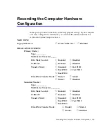
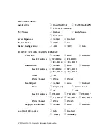
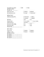
Page 63: ...clude all the fields listed here or may include additional fields Field names and order of appearance can vary according to the version of the BIOS basic input output system on your computer You can use the configuration listing at the back of this manual to record information specific to your computer See Recording the Computer Hardware Configuration on page 125 Fill it out as you complete your S...

Page 64: ...ent menu Left Arrow and Right Arrow keys Keypad arrow keys Select a different menu Pressing ESC at the Main menu brings you to the Exit menu Up Arrow and Down Arrow keys Keypad arrow keys Move the cursor up and down between fields Tab Moves the cursor forward through the cells for a highlighted field If the field has only one cell the Tab key moves the cursor down to the next field Tab Shift Moves...

Page 65: ...nd to go to the last page To exit the help window press Enter or Esc If your computer will not boot after you have changed settings in System Setup and exited the program reboot and press F2 to reenter System Setup Once in System Setup you can try to change the values that caused your computer boot to fail If the problem persists press F9 to load the default values Main Menu When you open System S...

Page 66: ...he values for the other fields in the submenu Manually set the other fields in this submenu only if the drive you have installed in your computer is not recognized by System Setup Set the Auto option of the Type field in the Secondary Master submenu to enable the system to boot from Bootable CD ROMs you will also need to check the boot device priority field and Bootable CD check field After you ma...

Page 67: ...er performance Transfer Mode Selects the method for transferring data between the hard drive and system memory Refer to your drive s user documentation to specify the correct option for this field Options are Standard Fast PIO 1 Fast PIO 2 Fast PIO 3 and Fast PIO 4 Ultra DMA Mode Enables the hard drive to use ultra DMA direct memory access transfer mode to transfer data between the drive and syste...

Page 68: ...ns the I O Device Configuration submenu if you press Enter when this field is highlighted If you attempt to set two ports to the same settings the fields will be marked with asterisks The submenu contains these fields Serial port Configures serial port The options for this field are Enabled default and Disabled If you set this field to Enabled you can set the Base I O Address field to 3F8 IRQ4 def...

Page 69: ...isk Access Mode Enables your computer s operating system to work with drives larger than 540 MB Choose DOS default for Microsoft operating systems Choose Other for any other operating systems Security Menu Selecting Security from the menu bar displays the Security menu Your computer s advanced security system allows you to set two different passwords to prevent unauthorized access to system resour...

Page 70: ... with the settings in the Power Management option of Control Panel But if your computer has DOS Windows 95 or Windows NT 4 0 the Power Management works with the settings in System Setup Intel R Speedstep TM When CPU supports Speedstep TM this field will appear on this menu The main idea of Speedstep is to save the power The CPU supported by the Speedstep adjusts its speed according to the power su...

Page 71: ... Time field is set Resume On Modem Ring Enables the computer to resume operation from rest mode in the event of modem communication The computer will resume only if the Suspend Mode field is set to Save to RAM not Save To Disk The default setting is Off Windows 98 does not use this item Resume On Time Enables the computer to resume operation from rest mode at a scheduled time The computer will res...

Page 72: ...ich the computer attempts to boot from different devices The field has four options Diskette Drive Removable Devices Hard Drive and ATAPI CD DVD ROM Drive To choose a device as the first second or third boot device 1 Press Enter at the Boot Device Priority field 2 Highlight the option with the Up Arrow or Down Arrow key 3 Use keys until the option moves up or down in the list of options and the nu...

Page 73: ...ad Setup Defaults Loads the default values for all System Setup parameters When you select this option and press Enter a message appears asking if you want to load the default configuration Choose Yes and press Enter to load default settings and remain in System Setup Choos No and press Enter to retain your changes and remain in System Setup Discard Changes Enables you to discard the selections yo...

Page 74: ...mputer such as in a network environment a supervisor password can prevent unauthorized access to certain security options Choose the type of password security that is appropriate for your work If you want to set a user password you must set a supervisor password first Creating a Password To create a password 1 At startup press F2 to open System Setup 2 Use the Right Arrow key to select the Securit...

Page 75: ... open System Setup 2 Type your password when prompted and press Enter 3 Use the Right Arrow key to select the Security menu 4 Use the Down Arrow key to select Set Supervisor Password or Set User Password 5 Press Enter The computer prompts you to enter the current password 6 Press Enter The computer prompts you to enter a password Do not type anything 7 Press Enter The computer prompts you to re en...

Page 76: ...t field in System Setup For more information about the Password on boot field see Security Menu on page 69 Locking the Keyboard The keyboard lock enables you to protect your system when you walk away fro it for a time To use the keyboard lock you must first enable a password through System Setup See Creating a Password on page 74 for instructions To lock your keyboard press Fn F7 To unlock your ke...

Page 77: ...in System Setup have no effect on Windows 98 Me Battery low and battery very low warnings are configured using the Power Management option If you want to use Hibernation function in ACPI mode Windows 98 Me then click Start Settings Control Panel and double click Power Management icon Select Hibernate on the When I press the sleep button on my computer field in Advanced tap Then you can use the pow...

Page 78: ...urned off During save to disk mode the DRAM and video memory are saved to the hard drive and are restored when your computer resumes operation You can press Fn F11 Rest to manually place your computer into Suspend mode When you use the Fn F11 Rest key combination your computer may postpone entering Suspend mode during a critical operation such as reading from or writing to the hard drive To resume...

Page 79: ... because of a low battery charge When the computer is in save to disk mode you can remove and replace the battery Using PowerProfiler PowerProfiler enables you to set power management options for computer shipped with Windows NT installed This section could differ depend on your computer specification To open the PowerProfiler window double click the battery icon on the right corner of the Windows...

Page 80: ...e time to 0 in System Setup and set the actual resume time that you desire in PowerProfiler PowerProfiler maintains the accuracy of the system clock when the computer resumes from rest mode If PowerProfiler is closed or removed from your hard drive your system clock may not be accurate when your computer resumes from rest mode For more information on PowerProfiler see the Help option in the PowerP...

Page 81: ...ordered starting from DVD CD ROM Use DVD Software CD in this process Before you set partition and format HDD set Fixed Disk Boot Sector to Normal in Security menu of System setup To create FDISK 1 Set the system boot with CD ROM press F8 key to boot with Safe mode command prompt only 2 Operate Fdisk exe type A fdisk and press Enter 3 When Do you wish to enable large disk support Y N shows select Y...

Page 82: ...sk exe as follows 3 Type E sysutil phdisk c 143360 p and press Enter 143360 is calculated as below formula and it could be different according to system memory 143360 system memory 64MB video memory 8MB extended memory 64MB buffer space 1MB x1024 4 Press any key to restart the system To format the HDD 1 Boot system by CD ROM 2 Operate Format exe type A format c s and press Enter 3 Warning message ...

Page 83: ...stem Setup set Diskette Drive as the first boot device and CD ROM Drive as the second see Using System Setup on page 63 for information on setting options See the documentation that accompanied your operating system for detailed information on installation and setup To re install your operating system 1 Turn your machine on 2 During the Boot Sequence press F2 to enter System Setup 3 Insert the Sys...

Page 84: ... have any data files or other software that you do not want to lose make a backup to diskette by using the Backup utility or by copying the files or software directly to diskettes before proceeding To re install your original applications and drivers Use the System Software CD ROM included in the packing And follow the instruction in the CD cover ...

Page 85: ...eral the more pixels the LCD can display the better the image Your LCD screen is XGA In XGA the screen has a maximum display of 1024x768 about 800 000 pixels The number of colors the LCD can display is measured by how many bits the LCD uses to represent each pixel 8 bit color can support 256 different colors 16 bit color can support 64 K 65 536 colors 24 bit color can support 16 M 16 8 million col...

Page 86: ...e is not available in Windows NT If you wish you can adjust the display settings by selecting a monitor type 1 Click the Start button on the Windows taskbar 2 Select Settings 3 Click Control Panel The Control Panel window appears 4 Double click the Display icon The Display Properties window appears 5 Click the Settings tab The Settings screen appears 6 Click the Advanced button The Advanced Proper...

Page 87: ...resolution and frequency when an external monitor is not present 13 Click the Next button 14 The Update Device Driver Wizard screen appears showing the driver location of the device you have selected Click the Next button 15 Follow any prompts that appear on the screen Changing Color Depth and Resolution To change the colour depth and resolution of your LCD or external monitor 1 Click the Start bu...

Page 88: ... depth you want 7 To change the resolution click and drag the knob under the Screen area until you select the resolution you want 8 Click the OK button 9 Follow the prompts that appear on the screen Changing the Video Driver It is possible that you may want to update your video driver or that your installed video driver has become corrupt so that the display is unusable ...

Page 89: ...cate driver you want to install Click the OK button 10 Select the new driver in the Select Device screen and click the Ok button 11 Click the Next button to install the new driver and follow any directions on the screen to finish setting the display properties Windows NT 4 0 1 Log on to the computer as supervisor The Invalid Display Settings window may appear 2 Click on the Start Button and the St...

Page 90: ...en successfully copied 11 Click OK Remove the disk from the floppy drive Close the open windows on the screen 12 Click Yes when prompted to restart the computer As the computer restarts select Windows NT Workstation Version 4 00 as the operating system andpress Enter 13 Log on as supervisor The Invalid Display Settings window appears 14 Click the OK button Click the Test button at the Display Prop...

Page 91: ...utton and locate driver you want to install Click the OK button 10 Click the Next button to install the new driver and follow any directions on the screen to finish the display properties setting 2nd Method 1 Click on the Start button and the Start menu appears 2 Select Settings and click on Control Panel double click on Display The Display Properties window appears 3 Select Settings tab 4 Click t...

Page 92: ...hile TV is ON pressing Fn CRT LCD cause TV Out disable Then you should follow from step4 DOS mode you should restart To enable TV out 1 Connect the TV to the TV Out port using an appropriate cable 2 Enter System Setup and under the Advanced menu set TV Standard to the appropriate standard for your TV see Using System Setup for information on setting options 3 Reboot your computer 4 You can see TV ...

Page 93: ... out then the system has not detected a TV check that the TV standard in the System Setup is set correctly and that the TV is turned on and connected properly And you can not use TV out port in DOS mode 12 Click OK and follow the prompts that appear on the screen ...

Page 94: ...s tab 4 Click the second monitor among two monitor pictures 5 When Do you want to enable this monitor message appears then selectYes 6 Click Apply or OK To confirm whether the system is set properly with Duo View mode 1 Open Display properties and click Settings tab 2 Place the mouse pointer on the first monitor picture and click over a second then digit number 1 will be shown on the first actual ...

Page 95: ... Click Apply or OK Limits and cautions of using Duo View mode The supporting capabilities of the primary monitor and the secondary monitor are different Primary CRT Controller Capabilities VGA Mode Accelerator Mode Hardware Overlay Hardware Cursor and Hardware Icon Ratiometric Expansion from up to 1024x768 source Secondary CRT Controller Capabilities No VGA Mode Accelerator Mode No Hardware Overla...

Page 96: ... color depth and refresh rate when Duo View mode is active are not supported because of video memory bandwidth limitation 2 When using Duo View in simultaneous display mode frame rates in Direct Draw applications are slightly lower because of the need to synchronize buffer flip 3 If the primary secondary monitor on Duo View mode is set to high resolution and high refresh rate display mode the full...

Page 97: ...unction So the programs using VPM Cirrus logic video port specification may not be supported 8 Changing Duo View mode to Single View mode while you maximize the window of a program such as Windows Explorer could fail Set the resolution of the secondary monitor lower than the primary monitor or adjust the window size to smaller not full screen 9 When you use CRT and TV together as the same primary ...

Page 98: ...mputer to use 32 bit PC Cards Windows 98 Me supports 32 bit and 16 bit PC Cards The SystemSoft CardWizard for Windows NT program provided with systems that ship from the factory with Windows NT installed also supports both 16 bit and 32 bit cards Zoomed video Both PC Card slots and the video chip on your computer support zoomed video When you install a zoom video PC Card in the upper or lower slot...

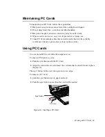
Page 99: ...hat extend from the back of the cards Be careful not to bend or put excessive strain on these cables Using PC Cards You can install PC Cards while the computer is on To insert a PC Card into a slot 1 Push the slot door in with the PC Card 2 Align the card with a slot and insert the card into the slot until it locks in place Figure 23 The eject button for the card slot operates in two steps To remo...

Page 100: ...t Windows NT Systemsoft Card Wizard is shipped with this notebook computer that use Windows NT as the operating system When you install a PC Card CardWizard attempts to configure it automatically If Card Wizard successfully assigns system resources to your card the computer beeps twice If CardWizard cannot automatically configure your PC Card the computer beeps once and a message appears telling y...

Page 101: ...this message Modem and ATA cards can be inserted and removed while the computer is on Before you remove a modem or ATA card from your computer stop the card through the CardWizard program or you may lose data To stop and remove a PC Card from your computer 1 In the SystemSoft CardWizard screen click with the right mouse button on the name of the card you want to remove 2 Click Stop in the Actions ...

Page 102: ...de your computer s memory to a maximum of 256MB A CD ROM drive module A DVD ROM drive module A Superdisk LS 120 drive Docking options that enable you to use your computer like a desktop computer The options that are available may change periodically Contact your reseller for updated information on current and new options AC Adapter The optional AC adapter operates in the same way as the adapter th...

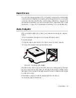
Page 103: ...les you to power your computer and charge the computer battery In an automobile through the 12 volt cigarette lighter socket To use the adapter 1 Plug the adapter cable into the AC adapter connector on the computer 2 Connect the adapter to the cigarette lighter socket Figure 24 Connecting Auto Adapter The light on the adapter is green when the adapter is working properly The light may be red for a...

Page 104: ...nplug the auto adapter when starting and stopping the automobile engine Memory Modules You can increase system memory by installing optional memory modules You can install a 32 64 or 128 MB modules To avoid possible system problems use only approved memory modules in your computer Before You Install Memory To prevent personal injury and damage to the equipment follow the precautions listed here be...

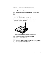
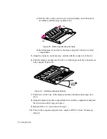
Page 105: ... bottom faces up 2 Using a screwdriver remove the screw that holds the memory module compartment door in place Figure 25 Figure 25 Removing the Memory Module Compartment Door 3 Grasp the edge of the door and pull the door off the chassis 4 Remove installed modules if necessary When removing modules pull on the plastic portion of the connector slots tabs only Do not pull on the metal part of the ta...

Page 106: ...he connector of the slot 6 Push the memory module into the slot at a slight angle until the connectors are fully engaged Figure 27 Figure 27 Installing a Memory Module 7 Push down on the edge of the memory module until the module snaps into place 8 Align the memory module compartment door with the compartment and push the door down until it snaps into place 9 Reinstall the screw you removed in ste...

Page 107: ...OM drive There is MPEG 2 software included with the drive that will enable you to play DVD movies from the DVD ROM drive Superdisk LS 120 Drive The LS 120 drive enables you to store 120 MB of data on a single 3 5 inch LS 120 diskette It is backward compatible with standard HD 1 44MB 3 5 inch diskettes and it can read and write to them up to three times faster The LS 120 drive fits in the Flex Bay ...

Page 108: ... hardware line that a device can use to send signals to the microprocessor When the device needs the microprocessor s service the device sends an interrupt request signal to the microprocessor The number of IRQs available for any computer is limited by industry standards Because it ships with numerous features this computer uses most of the available IRQs If you add another device to your computer...

Page 109: ...einstall SP4 The version of SP3 on your computer s hard drive includes the correct video driver for your system If possible always install this version on your computer To install SP3 1 Run the executable file On your computer s hard drive this file is located at C SP4 i386 update 2 Follow the instructions on the screen with these exceptions a When you are prompted to overwrite the uninstall direc...

Page 110: ... on your computer make sure that when you are prompted you do not overwrite the pcmcia sys file or you may be unable to use your computer If you install SP4 from any source other than your computer s hard drive the video driver that was installed on your computer at the factory is overwritten After you install the service pack you must reinstall the video driver the first time you restart your com...

Page 111: ...turn to the LCD panel Nothing appears on the external monitor when you switch the display to it Is the monitor properly connected to the computer Is the monitor s power cord connected to an AC wall outlet Check the brightness and contrast controls on the monitor Does the program appear on the LCD panel instead of the external monitor If so press Fn F5 to switch to the monitor Try turning the monit...

Page 112: ...ed The CMOS battery provides power to save the system BIOS information when the computer is turned off Normally the CMOS battery lasts for several years Do not attempt to open the chassisand replace this battery yourself or your warranty is void Have an authorized the manufacturer s service center replace the CMOS battery Infrared Problems If your computer s operating system is Windows 98 Me you c...

Page 113: ...itialization ATX3 W And add 9 as the external line prefix in our example of the phone number when using the dial command ATDT9 123 4567 Screen displays random or garbage characters during communications After your modem has connected to the on line service your screen may display garbage characters or after images in screen transitions This problem is caused by a mismatch of the terminal modes bet...

Page 114: ...hooting Depending on telephone line status or types of Fax machines programs that send receive the Fax Fax transmission reception may not work correctly In that case please try other Fax programs e g Microsoft Fax ...

Page 115: ...cm Height 1 51 in 38 4 cm Weight with integrated floppy drive Li Ion battery 14 1 TFT LCD weight saver 7 04 lb 3200 g Environment Ambient temperature operating 50o 90o F 10o 32o C Ambient temperature storage 23o 104o F 5o 40o C Relative humidity noncondensing operating 20 80 Relative humidity noncondensing storage 5 90 Altitude operating 0 to 8 000 ft 0 to 2 348 m Altitude storage 0 to 40 000 ft 0...

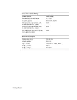
Page 116: ...arging time approximate with computer turned off typical 3 0 hr Charging time approximate with computer turned on typical 5 0 hr Average battery life with no power management enabled 3 5 hr External AC Adapter Operating voltage 100 240 VA Line frequency 50 60 Hz Input current 1 5 A 100 V 0 8 A 240 V Output current 3 15 A Output voltage 19 0 VDC ...

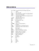
Page 117: ... interface BBS Bulletin board system BIOS Basic input output system C Centigrade CD Compact disc CD ROM Compact disc read only memory cm Centimeters COM Communication as in communication port CMOS Complementary metal oxide semiconductor DC Direct current DMA Direct memory access DPMS Display power management signaling DRAM Dynamic random access memory DSTN Double layer super twist nematic ECP Exte...

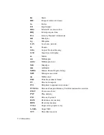
Page 118: ... display m Meters mA Milliampere mAhr Milliampere hour MB Megabyte mm millimeter MPEG Motion Picture Experts Group MPU Microprocessor unit ms Millisecond PDF Portable document format PC Personal computer PCI Peripheral component interconnect PCMCIA Personal Computer Memory Card International Association POST Power on self test PNP Plug and play PS 2 Personal System 2 RAM Random access memory ROM R...

Page 119: ...Abbreviations 119 USB Universal serial bus V Volt VAC Voltage alternating current VCC Voltage collector current VDC Voltage direct current whr Watt hour ...

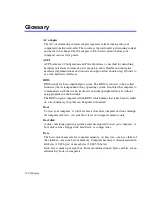
Page 120: ...tem It enables the computer to communicate with the screen keyboard and other peripheral devices without using programs on the hard disk The BIOS on your computer is flash BIOS which means that it has been recorded on a flash memory chip that can be updated if needed Boot To start your computer A cold boot resets the entire computer and runs through all computer self tests A warm boot clears out c...

Page 121: ... Setup settings and other parameters are maintained in CMOS memory Even when you turn your computer off the information in CMOS memory is saved COM port COM stands for communication COM ports are the serial ports in your computer Compact Disc A compact disc CD Conventional memory The first 640 KB of system memory Operating systems and application programs can directly access this memory without us...

Page 122: ...at of desktop hard drives However because of their smaller size the drives handle shock and vibration better than larger drives which is important for a notebook computer I O Input output Refers to peripheral devices such as printers that are addressed through an I O address I O address I O stands for input output Peripheral devices such as printers are addressed through the I O port address IRQ i...

Page 123: ...Ethernet adapters SCSI adapters ATA cards and memory cards PC slot The PC slot is the hardware slot in the computer where the PC Card is placed Pixel A pixel is an individual dot in a graphic displayed on your computer The pixels are so close together that they look as though they are connected An LCD screen displays thousands or millions of pixels Plug and Play A plug and play operating system au...

Page 124: ... the same as RAM Sector Also known as disk sector The portion of a track that is numbered and can hold a specified number of characters usually 512 KB Shadow RAM A write protected area of RAM that contains a copy of the BIOS As the computer boots the BIOS is copied from its permanent location in ROM to RAM The BIOS can be executed much faster in RAM than in ROM The BIOS remains in shadow RAM until...

Page 125: ... MB 3 1 2 Disabled IDE ADAPTER SUBMENU Primary Master Type __________ Multi Sector Transfers _____ LBA Mode Control Enabled Disabled 32 Bit I O Enabled Disabled Transfer Mode Standard Fast PIO 1 Fast PIO 2 Fast PIO 3 Fast PIO 4 Ultra DMA Transfer Mode Mode 0 Mode 1 Mode 2 Disabled Secondary Master Type ___________ Multi Sector Transfers _________ LBA Mode Control Enabled Disabled 32 Bit I O Enable...

Page 126: ...ENU Serial port Enabled Auto Disabled BaseI O Address 3F8 IRQ 4 2F8 IRQ 3 3E8 IRQ 4 2E8 IRQ 3 Infrared port Enabled Auto Disabled BaseI O Address 3F8 IRQ4 2F8 IRQ 3 3E8 IRQ 4 2E8 IRQ 3 Mode FIR DMA Channel DMA 3 DMA 1 Parallel port Enabled Auto Disabled Mode Output only Bi directional EPP ECP BaseI O Address 378 IRQ 378 IRQ 5 278 IRQ 7 278 IRQ 5 3BC IRQ 7 3BC IRQ 5 DMA Channel DMA 1 DMA 3 Floppy d...

Page 127: ...y Automatic Disabled Idle Mode Off On Suspend Mode Save to RAM Save To Disk Suspend Timeout Off Time_________________ Resume On Modem Ring On Off Resume On Time On Off Resume Time ________________________ BOOT MENU Logo Screen Enabled Disabled Summary screen Enabled Disabled Boot Device Priority Boot option 1 ________________________ Boot option 2 ________________________ Boot option 3 ___________...

Page 128: ...indows and Windows NT are registered trademarks of Microsoft Corporation This product incorporates copyright protection technology that is protected by method claims of certain U S patents and other intellectual property rights owned by Macrovision Corporation and other rights owners Use of this copyright protection technology must by authorized by Macrovision Corporation and is intended for home ...

Page 129: ...re unable to insert the plug into the outlet contact your electrician to replace your obsolete outlet Do not allow anything to rest on the power cord Do not place this product in a location where someone may trip over the cord If an extension cord is used with this product make sure that the total of the ampere ratings on the products plugged into the extension cord do not exceed the extension cor...

Page 130: ...id has been spilled into product If the product has been exposed to rain or water If the product does not operate normally when the operating instructions are followed adjust only those controls that are covered by the operating instructions Improper adjustment of other controls may result in damage If the product exhibits a distinct change in performance Battery Disposal Warning Do not put rechar...

Page 131: ...elevision reception which can be determined by turning the equipment off and on the user is encouraged to try to correct the interference by one or more of the following measures Reorient or relocate the receiving antenna Increase the separation between the equipment and receiver Connect the equipment into an outlet on a circuit different from that to which the receiver is connected Consult the de...

Page 132: ...mined by total RENs contact the local telephone company to determine the maximum REN for the calling area If the terminal equipment causes harm to the telephone network the Telephone Company will notify you in advance that temporary discontinuance of service may be required But if advance notice is not practical the telephone company will notify the customer as soon as possible Also you will be ad...

Page 133: ... this information into your fax machine refer to your communications software user manual CTR21 Statement The equipment has been approved in accordance with Council Decision 98 482 EC for pan European single terminal connection to the public switched telephone network PSTN However due to differences between the individual PSTNs provided in different countries the approval does not of itself give a...

Page 134: ...E MED OPTISKE INSTRUMENTER LUOKAN 1 LASERLAITE VAROITUS LAITTEEN KÄYTTÄMINEN MUULLA KUIN TÄSSÄ KÄYTTöOHJEESSA MAINITULLA TAVALLA SAATTAA ALTISTAA KÄYTTÄJÄN TURVALLISUUSLUOKAN 1 YLITTÄVÄLLE NÄKYMÄTTöMÄLLE LASERSÄTEILYLLE KLASS 1 LASERAPPARAT VARNING OM APPARATEN ANVÄNDS PÅ ANNAT SÄTT ÄN I DENNA BRUKSANVISNING SPECIFICERATS KAN ANVÄNDAREN UTSÄTTAS FöR OSYNLIG LASER STRÅLNING SOM öVERSKRIDER GRÄNSEN ...

Page 135: ... 8m and a maximum of 9 75 feet 3 0m All power cord sets must be approved by an acceptable accredited agency responsible for evaluation in the country where the power cord set will be used The power cord set must have a minimum current capacity of 7 A and a nominal voltage rating of 125 or 250 volts AC as required by each country s power system The appliance coupler must meet the mechanical configu...

Page 136: ... cord must be Type SVT or equivalent No 18 AWG Wall plug must be a two pole grounding type Appliance coupler flexible cord and wall plug must bear a T mark and registraion number in accordance with the Japanese Dentori Law Flexible cord must be Type VCT or VCTF 3 conductor 0 75 mm conductor size Wall plug must be a two pole grounding type with a Japanese Industrial Standard C8303 15 A 125V configu...

Reviews: