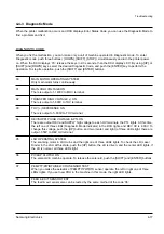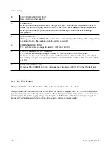
4-4-3 Diagnostic Mode
When the printer malfunction occurs and DCU displays Error Status Code, you can use the Diagnostic Mode to
find a problem and fix it.
DIAGNOSTIC CODE
When you fix the malfunction, you can make only a unit of machine operated in Diagnostic mode. To enter
Diagnostic mode, push three buttons ( [DOWN], [SHIFT], [STOP] ) simultaneously and turn the printer power
on. When the DCU displays ‘78’, release the keys in 2-3 seconds, then the DCU displays ‘00’. By using [UP] or
[SHIFT] and [DOWN] keys, select the desired Diagnostic Code, and push the [ENTER] key to perform the
operation. To stop its operation, push the [SHIFT] and [ENTER] buttons.
00
MAIN MOTOR OPERATING SYSTEM
Only main motor turns continuously.
01
MAIN HIGH VOLTAGE ON
There is output of -1400V to MHV terminal.
02
TRANSFER HIGH VOLTAGE (-) ON
There is output of -800V to THV terminal.
03
THV (+) REFERENCE ON
There is output of +800V to THV terminal.
04
DEV/SUPPLY HIGH VOLTAGE & PTL ON
There are output DEV and SUPPLY high voltage to each HV terminals, the PTL lights. At this time,
the left one of three LEDs (Diagnostic Mode Indicator) in the DCU lights, and DEV HV is -300V. To
change this voltage, push the [UP] button, and two (center and right) of three LEDs light, there are
output -350V to DEV HV terminal.
05
LSU OPERATING SYSTEM
The scanning motor in LSU turns and the right one of three LEDs lights. To check the LD (Laser
Diode) in the LSU at this state, push the [UP] button, the LD is driven, and the center LED lights. If
the LD is normal, all three LEDs light.
06
PICKUP CLUTCH ON
The solenoid in machine operate. To release the solenoid, push the [SHIFT] and [ENTER] buttons.
07
PEMPTY/PWIDTH/NEW CRU SENSOR TEST
When you make the actuator of PEMPTY/PWIDTH sensor operate, the left or right one of three
LEDs lights. If you set new CRU in the machine in this mode, the right LED lights.
08
FEED & EXIT SENSOR TEST
The feed & exit sensor also can be tested by the same method of the code ‘06’.
4-17
Samsung Electronics
Troubleshooting
Summary of Contents for ML-5200A
Page 50: ...5 14 Samsung Electronics Exploded Views and Parts List MEMO ...
Page 63: ...PCB Diagrams Samsung Electronics 9 5 9 5 HVPS PCB Diagram TOP ...
Page 68: ...MEMO Samsung Electronics 8 2 ...
Page 69: ...10 1 Main Circuit Diagram 1 9 Samsung Electronics 10 1 10 Schematic Diagrams ...
Page 70: ...Schematic Diagrams 10 2 Samsung Electronics Main Circuit Diagram 2 9 ...
Page 71: ...Main Circuit Diagram 3 9 Samsung Electronics 10 3 Schematic Diagrams ...
Page 72: ...Schematic Diagrams 10 4 Samsung Electronics Main Circuit Diagram 4 9 ...
Page 73: ...Main Circuit Diagram 5 9 Samsung Electronics 10 5 Schematic Diagrams ...
Page 74: ...Schematic Diagrams 10 6 Samsung Electronics Main Circuit Diagram 6 9 ...
Page 75: ...Main Circuit Diagram 7 9 Samsung Electronics 10 7 Schematic Diagrams ...
Page 76: ...Schematic Diagrams 10 8 Samsung Electronics Main Circuit Diagram 8 9 ...
Page 77: ...Main Circuit Diagram 9 9 Samsung Electronics 10 9 Schematic Diagrams ...
Page 78: ...Schematic Diagrams 10 10 Samsung Electronics 10 2 Engine Circuit Diagram 1 2 ...
Page 79: ...Engine Circuit Diagram 2 2 Samsung Electronics 10 11 Schematic Diagrams ...
Page 80: ...Schematic Diagrams 10 12 Samsung Electronics 10 3 SMPS Circuit Diagram ...
Page 81: ...10 4 SENSOR Circuit Diagram Samsung Electronics 10 13 Schematic Diagrams ...
Page 82: ...Schematic Diagrams 10 14 Samsung Electronics 10 5 PTL Circuit Diagram ...
Page 83: ...10 6 HVPS Circuit Diagram 1 3 Samsung Electronics 10 15 Schematic Diagrams ...
Page 84: ...Schematic Diagrams 10 16 Samsung Electronics HVPS Circuit Diagram 2 3 ...
Page 85: ...HVPS Circuit Diagram 3 3 Samsung Electronics 10 17 Schematic Diagrams ...

