4. Troubleshooting
4-1 Abnormal Image Printing and Defective Roller
If abnormal image prints periodically, check the parts shown below.
Samsung Electronics
4-1
No
Roller
Abnormal image period
Kind of abnormal image
1
OPC Drum
94.3mm
White spot
2
Charge Roller
37.7mm
Black spot
3
Supply Roller
40.0mm
Horizontal density band
4
Develop Roller
46.1mm
Horizontal density band
5
Transfer Roller
47.1mm
Black side contamination/transfer fault
6
Heat Roller
56.1mm
Black spot and fuser ghost
7
Pressure Roller
56.2mm
Black side contamination
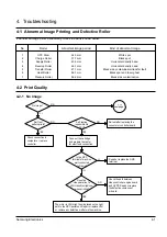
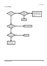
Check connection to
computer or replace
controller.
Take out the cartridge
and prepare the tester
for electronic connection.
Repair or replace the GND
terminal.
Check the path between
video controller, engine board
and HVPS. Repair or replace
the defective component
or board.
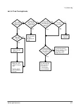
The mirror in LSU might be misplaced so the light
path to the OPC deviates ->Repair or replace LSU
or remove any defective matters in the machine.
Self test
pattern prints?
No image?
Self testing
is possible via
DCU?
Is the OPC
terminal of machine
well-connected
to Frame?
Does the
video data line to
LSU transit to High/Low
when printing?
Re-test after replacing the
conector or controller board.
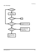
A on
next page
NO
NO
NO
NO
NO
YES
YES
YES
YES
YES
4-2 Print Quality
4-2-1 No Image
Summary of Contents for ML-5200A
Page 50: ...5 14 Samsung Electronics Exploded Views and Parts List MEMO ...
Page 63: ...PCB Diagrams Samsung Electronics 9 5 9 5 HVPS PCB Diagram TOP ...
Page 68: ...MEMO Samsung Electronics 8 2 ...
Page 69: ...10 1 Main Circuit Diagram 1 9 Samsung Electronics 10 1 10 Schematic Diagrams ...
Page 70: ...Schematic Diagrams 10 2 Samsung Electronics Main Circuit Diagram 2 9 ...
Page 71: ...Main Circuit Diagram 3 9 Samsung Electronics 10 3 Schematic Diagrams ...
Page 72: ...Schematic Diagrams 10 4 Samsung Electronics Main Circuit Diagram 4 9 ...
Page 73: ...Main Circuit Diagram 5 9 Samsung Electronics 10 5 Schematic Diagrams ...
Page 74: ...Schematic Diagrams 10 6 Samsung Electronics Main Circuit Diagram 6 9 ...
Page 75: ...Main Circuit Diagram 7 9 Samsung Electronics 10 7 Schematic Diagrams ...
Page 76: ...Schematic Diagrams 10 8 Samsung Electronics Main Circuit Diagram 8 9 ...
Page 77: ...Main Circuit Diagram 9 9 Samsung Electronics 10 9 Schematic Diagrams ...
Page 78: ...Schematic Diagrams 10 10 Samsung Electronics 10 2 Engine Circuit Diagram 1 2 ...
Page 79: ...Engine Circuit Diagram 2 2 Samsung Electronics 10 11 Schematic Diagrams ...
Page 80: ...Schematic Diagrams 10 12 Samsung Electronics 10 3 SMPS Circuit Diagram ...
Page 81: ...10 4 SENSOR Circuit Diagram Samsung Electronics 10 13 Schematic Diagrams ...
Page 82: ...Schematic Diagrams 10 14 Samsung Electronics 10 5 PTL Circuit Diagram ...
Page 83: ...10 6 HVPS Circuit Diagram 1 3 Samsung Electronics 10 15 Schematic Diagrams ...
Page 84: ...Schematic Diagrams 10 16 Samsung Electronics HVPS Circuit Diagram 2 3 ...
Page 85: ...HVPS Circuit Diagram 3 3 Samsung Electronics 10 17 Schematic Diagrams ...


