
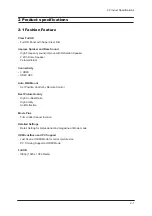


2 Product Specifications
2-3
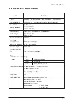
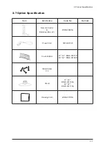
2-3 LE40N87BDX Specifications
Item
LCD Panel
Scanning Frequency
Display Colors
Description
LTA400HT-LH1, SPVA 92% ZBD, 40inch FHD, 0.416(H) x 0.154(W) x 3mm
Horizontal : 30 kHz ~ 80 kHz (Automatic) / Vertical : 56 Hz ~ 75 Hz (Automatic)
16.7 M colours
Analog 0.7 Vp-p
±
5% positive at 75Ω , internally terminated
Maximum Resolution
Input Video Signal
166.8 MHz
Maximum Pixel Clock rate
AC 220 ~ 240 V, 50/60 Hz
AC power voltage & Frequencya
240 W <1W
Power Consumption
75Ω
Antenna Input
-MAX Internal speaker Out : Right : 10W / Left : 10W
-BASS Control Range : -8 dB ~ + 8dB
-TREBLE Control Range : -8 dB ~ +8 dB
-Headphone Out : 10 mW MAX
-Output Frequency :
RF : 80 Hz ~ 15 kHz
A/V : 80 Hz ~ 20 kHz
Sound Characteristic
TV System
Environmental Considerations
Tuning
System
Sound
Frequency Synthesize
PAL, SECEM
MONO, STEREO, NICAM
22 Kg
Weight
Set(After installation Stand)
1041 X 97 X 615 mm / Without stand
1041 X 290 X 671 mm / After installation Stand
Operating Temperature : 50
°
F ~ 104
°
F (10
°
C ~ 40
°
C)
Operating Humidity : 10 % ~ 80 %
Storage Temperature : -4
°
F ~ 113
°
F (-20
°
C ~ 45
°
C)
Storage Humidity : 5 % ~ 95 %
Dimensions(W x D x H)
Set
819.36(H) mm / 460.89(V) mm
Active Display
Horizontal/Vertical
Horizontal : 1920 Pixels
Vertical : 1080 Pixels
Input Sync Signal
Type : Seperate H/V
Level : TTL level
Summary of Contents for LE40N87BDX
Page 13: ...2 Product Specifications 2 8 Memo...
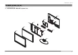
Page 37: ...11 Disassembly and Reassembly 11 6 Memo...
Page 41: ...4 Troubleshooting 4 4 WAVEFORMS 1 R G B Output Signal of IC2001...
Page 43: ...4 Troubleshooting 4 6 2 Digital Output Data of IC4001 3 Signal of HDMI Data...
Page 45: ...4 Troubleshooting 4 8 WAVEFORMS 4 Tuner_CVBS Output Signal 3 CVBS Output Signal...
Page 47: ...4 Troubleshooting 4 10 WAVEFORMS 4 CVBS Output Signal...
Page 49: ...4 Troubleshooting 4 12 2 Digital Output Data of IC2001 5 Analog Signal Y C to IC2001 WAVEFORMS...
Page 67: ...3 Alignments and Adjustments 3 16 Memo...
Page 69: ...7 Block Diagrams 7 2 Memo...
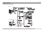
Page 71: ...12 PCB Diagram 12 2 12 2 IP Board Diagram 37...
Page 72: ...12 PCB Diagram 12 3 12 3 IP Board Diagram 40...
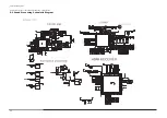
Page 73: ...12 PCB Diagram 12 4 12 4 IP Board Diagram 46...
Page 74: ...12 PCB Diagram 12 5 12 5 IP Board Diagram 52...
Page 75: ...12 PCB Diagram 12 6 Memo...
Page 81: ...8 Wiring Diagrams 8 6 8 4 Power Board Layout...
Page 84: ...8 9 8 Wiring Diagrams...
Page 87: ...8 Wiring Diagrams 8 12 Memo...
Page 122: ...13 Circuit Descriptions 13 3 13 2 Main Block...
Page 123: ...13 Circuit Descriptions 13 4 13 3 IP Board...
Page 129: ...10 Operating Instructions and Installation 10 6 Memo...
Page 137: ...14 Reference Infomation 14 8 14 3 2 Supported Modes 1...
Page 138: ...14 Reference Infomation 14 9 14 3 3 Supported Modes 2...
Page 139: ...14 Reference Infomation 14 10 14 3 4 Supported Modes 3...
Page 150: ...Memo 1 Precautions 1 4...


