


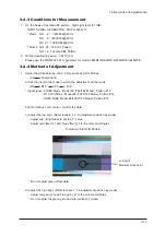


3 Alignments and Adjustments
3-11
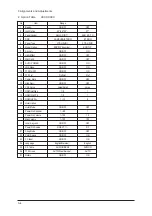
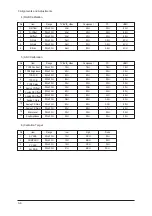
11. Checksum 7A72
12. Reset
13. Spread Spectrun
No
Item
Range
1
2
3
4
5
6
7
Spectrum
Delta
Positive
Negative
Speed
Time
FBE Spectrum
ON/OFF
-128 ~ +128
0~99
0~99
0~7
0~7
0~5
ON
0
8
2
0
4
0
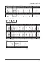
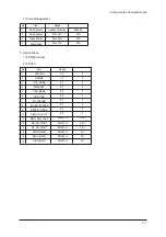
10. W/B MOVIE
1
2
3
4
5
6
7
8
9
10
8
9
10
11
12
13
14
15
16
17
18
19
20
21
22
WB Movie
Color Mode
Color Tone
Msub Brigh
Msub Contr
W1_RGAIN
W1_BGAIN
W1_R_OFFS
W1_B_OFFS
W2_RGAIN
W2_BGAIN
W2_R_OFFS
W2_B_OFFS
NO_RGAIN
NO_BGAIN
NO_R_OFFS
NO_B_OFFS
C2_RGAIN
C2_BGAIN
C2_R_OFFS
C2_B_OFFS
Movie Contr
Movie Brigh
Movie Color
Movie Sharp
ON/OFF
Movie
0~255
0~255
0~255
0~255
0~255
0~255
0~255
0~255
0~255
0~255
0~255
0~255
0~255
0~255
0~255
0~255
0~255
0~255
0~100
0~100
0~100
0~100
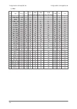
No
Item
Range
OFF
Movie
Cool1
128
128
157
76
119
138
142
48
129
143
141
104
126
136
124
142
128
128
100
45
55
75
TV/AV/S_Video
OFF
Dynamic
Cool1
128
128
161
74
119
140
143
47
127
145
139
102
125
133
122
141
129
127
100
45
55
75
Component
OFF
Dynamic
Cool1
128
128
144
117
127
110
149
93
124
110
137
123
126
114
123
156
117
116
100
45
55
75
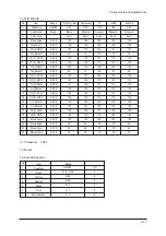
PC
OFF
Dynamic
Cool1
128
128
161
76
118
141
142
51
128
143
141
104
121
133
125
143
128
128
100
45
55
75
HDMI
OFF
Dynamic
Cool1
128
128
157
76
119
138
142
48
129
143
141
104
126
136
124
142
128
128
100
45
55
75
Scart1/2
Summary of Contents for LE40N87BDX
Page 13: ...2 Product Specifications 2 8 Memo...
Page 37: ...11 Disassembly and Reassembly 11 6 Memo...
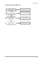
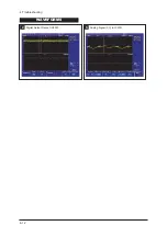
Page 41: ...4 Troubleshooting 4 4 WAVEFORMS 1 R G B Output Signal of IC2001...
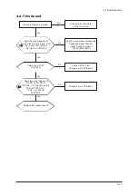
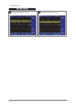
Page 43: ...4 Troubleshooting 4 6 2 Digital Output Data of IC4001 3 Signal of HDMI Data...
Page 45: ...4 Troubleshooting 4 8 WAVEFORMS 4 Tuner_CVBS Output Signal 3 CVBS Output Signal...
Page 47: ...4 Troubleshooting 4 10 WAVEFORMS 4 CVBS Output Signal...
Page 49: ...4 Troubleshooting 4 12 2 Digital Output Data of IC2001 5 Analog Signal Y C to IC2001 WAVEFORMS...
Page 67: ...3 Alignments and Adjustments 3 16 Memo...
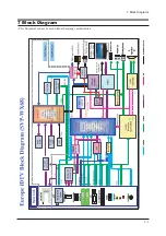
Page 69: ...7 Block Diagrams 7 2 Memo...
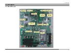
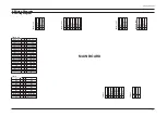
Page 71: ...12 PCB Diagram 12 2 12 2 IP Board Diagram 37...
Page 72: ...12 PCB Diagram 12 3 12 3 IP Board Diagram 40...
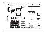
Page 73: ...12 PCB Diagram 12 4 12 4 IP Board Diagram 46...
Page 74: ...12 PCB Diagram 12 5 12 5 IP Board Diagram 52...
Page 75: ...12 PCB Diagram 12 6 Memo...
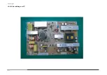
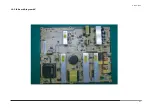
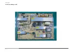
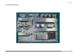
Page 81: ...8 Wiring Diagrams 8 6 8 4 Power Board Layout...
Page 84: ...8 9 8 Wiring Diagrams...
Page 87: ...8 Wiring Diagrams 8 12 Memo...
Page 122: ...13 Circuit Descriptions 13 3 13 2 Main Block...
Page 123: ...13 Circuit Descriptions 13 4 13 3 IP Board...
Page 129: ...10 Operating Instructions and Installation 10 6 Memo...
Page 137: ...14 Reference Infomation 14 8 14 3 2 Supported Modes 1...
Page 138: ...14 Reference Infomation 14 9 14 3 3 Supported Modes 2...
Page 139: ...14 Reference Infomation 14 10 14 3 4 Supported Modes 3...
Page 150: ...Memo 1 Precautions 1 4...


