ADDRESS SPACES
KS57C2308/P2308/C2316/P2316
2-12
STACK OPERATIONS
STACK POINTER (SP)
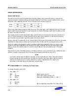
The stack pointer (SP) is an 8-bit register that stores the address used to access the stack, an area of data
memory set aside for temporary storage of data and addresses. The SP can be read or written by 8-bit control
instructions. When addressing the SP, bit 0 must always remain cleared to logic zero.
F80H
SP3
SP2
SP1
"0"
F81H
SP7
SP6
SP5
SP4
There are two basic stack operations: writing to the top of the stack (push), and reading from the top of the stack
(pop). A push decrements the SP and a pop increments it so that the SP always points to the top address of the
last data to be written to the stack.
The program counter contents and program status word are stored in the stack area prior to the execution of a
CALL or a PUSH instruction, or during interrupt service routines. Stack operation is a LIFO (Last In-First Out)
type. The stack area is located in general-purpose data memory bank 0.
During an interrupt or a subroutine, the PC value and the PSW are saved to the stack area. When the routine has
completed, the stack pointer is referenced to restore the PC and PSW, and the next instruction is executed.
The SP can address stack registers in bank 0 (addresses 000H-0FFH) regardless of the current value of the
enable memory bank (EMB) flag and the select memory bank (SMB) flag. Although general-purpose register
areas can be used for stack operations, be careful to avoid data loss due to simultaneous use of the same
register(s).
Since the
RESET
value of the stack pointer is not defined in firmware, we recommend that you initialize the stack
pointer by program code to location 00H. This sets the first register of the stack area to 0FFH.
NOTE
A subroutine call occupies six nibbles in the stack; an interrupt requires six. When subroutine nesting or
interrupt routines are used continuously, the stack area should be set in accordance with the maximum
number of subroutine levels. To do this, estimate the number of nibbles that will be used for the
subroutines or interrupts and set the stack area correspondingly.
+
+
PROGRAMMING TIP — Initializing the Stack Pointer
To initialize the stack pointer (SP):
1.
When EMB = "1":
SMB
15
; Select memory bank 15
LD
EA,#00H
; Bit 0 of SP is always cleared to "0"
LD
SP,EA
; Stack area initial address (0FFH)
←
(SP) – 1
2.
When EMB = "0":
LD
EA,#00H
LD
SP,EA
; Memory addressing area (00H–7FH, F80H–FFFH)
Summary of Contents for KS57C2308
Page 30: ...ADDRESS SPACES KS57C2308 P2308 C2316 P2316 2 22 NOTES ...
Page 168: ...SAM47 INSTRUCTION SET KS57C2308 P2308 C2316 P2316 5 94 NOTES ...
Page 170: ......
Page 206: ...POWER DOWN KS57C2308 P2308 C2316 P2316 8 8 NOTES ...
Page 210: ...RESET KS57C2308 P2308 C2316 P2316 9 4 NOTES ...
Page 222: ...I O PORTS KS57C2308 P2308 C2316 P2316 10 12 NOTES ...
Page 272: ...LCD CONTROLLER DRIVER KS57C2308 P2308 C2316 P2316 12 24 NOTES ...
Page 280: ...SERIAL I O INTERFACE KS57C2308 P2308 C2316 P2316 13 8 NOTES ...
Page 294: ...MECHANICAL DATA KS57C2308 P2308 C2316 P2316 15 2 NOTES ...
Page 310: ...KS57P2308 P2316 OTP KS57C2308 P2308 C2316 P2316 16 16 NOTES ...
Page 318: ......
Page 320: ......
Page 322: ......
Page 325: ......
Page 327: ......


