I/O PORTS
KS57C2308/P2308/C2316/P2316
10-8
PORT 2 CIRCUIT DIAGRAM
8
1, 4
1, 4
M
U
X
P2.0/TCLO0
P2.1
P2.2/CLO
P2.3/BUZ
PM2
Output
Latch
When a port pin acts as an output, its pull-up resistor is automatically
disabled, even though the port's pull-up resistor is enabled by bit settings
to the pull-up resistor mode register (PUMOD).
NOTE:
TCLO0
BUZ
CLO
PUMOD.2
V
DD
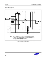
Figure 10-3. Port 2 Circuit Diagram
Summary of Contents for KS57C2308
Page 30: ...ADDRESS SPACES KS57C2308 P2308 C2316 P2316 2 22 NOTES ...
Page 168: ...SAM47 INSTRUCTION SET KS57C2308 P2308 C2316 P2316 5 94 NOTES ...
Page 170: ......
Page 206: ...POWER DOWN KS57C2308 P2308 C2316 P2316 8 8 NOTES ...
Page 210: ...RESET KS57C2308 P2308 C2316 P2316 9 4 NOTES ...
Page 222: ...I O PORTS KS57C2308 P2308 C2316 P2316 10 12 NOTES ...
Page 272: ...LCD CONTROLLER DRIVER KS57C2308 P2308 C2316 P2316 12 24 NOTES ...
Page 280: ...SERIAL I O INTERFACE KS57C2308 P2308 C2316 P2316 13 8 NOTES ...
Page 294: ...MECHANICAL DATA KS57C2308 P2308 C2316 P2316 15 2 NOTES ...
Page 310: ...KS57P2308 P2316 OTP KS57C2308 P2308 C2316 P2316 16 16 NOTES ...
Page 318: ......
Page 320: ......
Page 322: ......
Page 325: ......
Page 327: ......

