iDCS 100
INSTALLATION
TECHNICAL MANUAL
PART 4 JUNE 2002
4.2
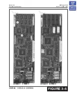
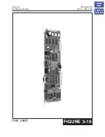
4.3 iDCS MEM4 CARD INDICATIONS
Having verified proper operation of the power supply, visually check the iDCS MEM4
card indications. The LED indications are as follow:
LED Indication
OFF
ON
1
Indicates whether the status of LAN transmit chip
(LST972, U13) is in normal or abnormal.
Abnormal
status
Normal
status
2
Indicates LAN link status
Link
No Link
3
Indicates whether there is LAN RX data or not
None
Exist
LED Indication Slow
Flicker
(500ms)
Fast Flicker
(200 ms)
4
RUN LED for MCP(MP)
Indicates the operation of MCP
Normal
operation
Booting
operation
5
RUN LED for LAN
Indicates the operation of LAN
Normal
operation
Booting
operation
4.4 PCB VERIFICATION
Before connecting all MDF cabling, plug in a test cable to the first S8DLI port. Connect
a display set and verify that it is working. Use maintenance programs
and
to verify the system version, software version and that all cards are
recognized by the CPU. Remove the test cable and plug in all amphenol-type cables to
the MDF. Proceed with the rest of the installation.
4.5 DEFAULT TRUNK AND STATION NUMBERING
Upon initial power up, the CPU reads each slot for the existence of a card and identifies
the type of card. It stores this as the default configuration.
The system assigns trunk numbers beginning with 701 and continues to 703 if one
S3TRK card has been installed or 706 if two S3TRK cards and so on.
Station numbers are assigned in the same manner. The lowest station is assigned
station number 201 and continues to 208 for a basic KSU or to 216 for system with one
S8DLI. Keyset daughter boards are assigned numbers beginning with 301 and
continue to 308. Default data assigns the keyset in the lowest port to the operator
group and all trunks ring that station until the default is changed.
Station and trunk numbers can be changed, rearranged and reassigned, as needed
using
HOME
PAGE
Table of
Contents

