iDCS 100
INSTALLATION
TECHNICAL MANUAL
PART 3 JUNE 2002
3.3
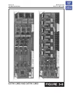
3.11 S6TRK CARD
There are no options to select on this card. Insert the S6TRK card into any universal
slot in the KSU or expansion cabinet
. Push firmly in the middle of both
card ejectors on each card to ensure that it is fully inserted into the back plane
connector.
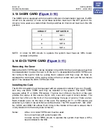
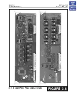
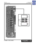
3.12 2 E&M 4 DLI CARD
This is the same card as used on the DCS Compact. The E&M trunk circuits on this
card can be set to provide either Type 1 or type 5 operation. Type 1 operation is used
when connecting to Telco circuits and type 5 is used when connecting “back to back”
across a private cable. Set the jumpers located between the two relays
according to the table below. Both of the jumpers for each circuit must be set to the
same type for correct operation.
CIRCUIT JUMPER POSITION TYPE
1 J1 T1
TYPE
1
1 J1 T5
TYPE
5
1 J2 T1
TYPE
1
1 J2 T5
TYPE
5
2 J3 T1
TYPE
1
2 J3 T5
TYPE
5
2 J4 T1
TYPE
1
2 J4 T5
TYPE
5
WARNING
: Turn the system off and remove the card from the system before
attempting to change jumper settings. 48 volts is present on the jumpers at all times
the system is turned on.
NOTE: When set to TYPE 1 the E&M Tie line circuits on this card are USOC TYPE
TL11M.
Insert the 2 E&M X 4 DLI card into any universal slot in the KSU or expansion cabinet
. Push firmly in the middle of both card ejectors on each card to ensure
that it is fully inserted into the back plane connector
HOME
PAGE
Table of
Contents

