background image

Alignment and Adjustments

4-20

Samsung Electronics

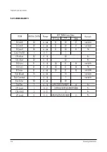
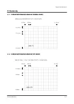
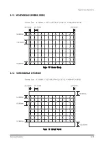
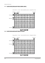
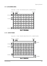
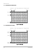
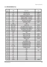
4-7-7   552W/5515W/5525W/553W/PTH5598 (NORMAL MODE)

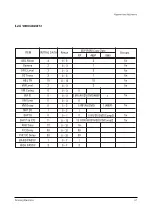
4-7-8   552W/5515W/5525W/553W/PTH5598 (DTV MODE)

Summary of Contents for HCN5527WX/XAA

Page 1: ...XAA ST54T8PCX XAX PROJECTION TV RECEIVER CONTENTS Precautions Reference Information Specifications Alignment and Adjustments Troubleshooting Exploded View and Parts List Electric Parts List Block Diag...

Page 2: ...s metal cabinets screwheads and control shafts The current measured should not exceed 0 5 milliamp Reverse the power plug prongs in the AC outlet and repeat the test Fig 1 1 AC Leakage Test 6 Antenna...

Page 3: ...appear to have overheated or that are otherwise damaged should be replaced with parts that meet the original specifications Always determine the cause of damage or overheat ing and correct any potent...

Page 4: ...hone jacks 6 Insulation Checking Procedure Disconnect the power cord from the AC source and turn the power switch ON Connect an insulation resistance meter 500V to the blades of the AC plug The insula...

Page 5: ...ldering iron when soldering or unsoldering ESDs 6 Use only an anti static solder removal device Many solder removal devices are not rated as anti static these can accumulate sufficient electrical char...

Page 6: ...Hertz Hour Inches Per Second Kilowatt hour Kilogram Kilohertz Kilohm Kilometer Kilometer Per Hour Kilovolt Kilovolt ampere Kilowatt Liter Megahertz MV MW M m A F H m s W mA mg mH mI mm ms mV nF pF Ib...

Page 7: ...fe Ground Green Y High High Frequency High Fidelity Inductance Capacitance Integrated Circuit Intermediate Frequency I O L L LED LF MOSFET MTS NAB NEC NTSC OSD PCB PLL PWM QIF R RC RF R Y SAP SAW SIF...

Page 8: ...the electron beam injected into the corners of CRT should increase and the focus dagradation by the difference of distances can be compensated Increasing the voltage is used as a method of increasing...

Page 9: ...Reference Information 2 4 Samsung Electronics 2 3 IC Line Up 2 3 1 Progressive...

Page 10: ...Reference Information Samsung Electronics 2 5...

Page 11: ...Reference Information 2 6 Samsung Electronics 2 4 MICOM IIC BUS LINE UP...

Page 12: ...Voltage W B Coordinates High Voltage FUSE Power Consumption Dimension Weight NTSC Progressive Scanning VHF CH2 CH13 75 ohm Unbalanced Video 45 75 MHz Sound 42 25 MHz Chrominance Subcarrier 42 17 MHz...

Page 13: ...MEMO 3 2 Samsung Electronics...

Page 14: ...ET 1080i OFFSET CONVERGENCE OFFSET VIDEO ADJUST 1 VIDEO ADJUST 2 VIDEO ADJUST 3 VIDEO ADJUST 4 OPTION E3h 98h 0ch RESET 02 05 03 1 When a RF signal is received MAIN MENU MENU DISPLAY CH UP DOWN Select...

Page 15: ...32 V Linearity 6 fix fix fix fix fix fix fix fix fix Upper Linearity 7 Lower Linearity 8 VSC 3 H Parabola 10 Upper Corner 32 Lower Corner 32 H Trapezium 32 Bow 32 Angel 32 V Position 32 CXA Left Blk...

Page 16: ...x fix fix fix fix fix fix Upper Linearity 0 Lower Linearity 0 VSC 0 H Parabola 0 Upper Corner 0 Lower Corner 0 H Trapezium 0 0 Bow 0 Angel V Position 0 0 0 0 0 0 0 0 0 0 0 0 0 0 0 0 28 36 CXA Left Blk...

Page 17: ...per Linearity 0 Lower Linearity 0 VSC 0 H Parabola 0 Upper Corner 0 Lower Corner 0 H Trapezium 0 Bow 0 Angel 0 V Position 0 0 0 0 0 0 0 0 0 0 0 0 0 0 0 0 CXA Left Blk CXA Right Blk 63 20 Remark ITEM I...

Page 18: ...e variable variable variable variable variable variable V Amp 15 V Shift 0 H EW 15 V Amp 1080i 15 V Shift 1080i 0 H EW 1080i 15 0 15 0 15 15 0 15 Remark ITEM INITIAL DATA Range RF 480P EEP ROM Copy Da...

Page 19: ...Driver 31 B Driver 31 Sub Bright 15 Sub Contrast 7 Sub Color 20 SubTint 7 CTI Level 1 CDL AXIS 2 LTI Level 0 20 20 20 1 31 31 31 15 7 20 31 31 31 20 20 20 31 31 31 20 20 20 10 8 AV SV DVD 480P 1 RF AV...

Page 20: ...KB Time 13 Y C Delay 30 PIP Y C Delay 30 BAND PASS F 1 HIGH PASS F 3 3 1 3 1 15 2 0 1 1 480P 2 RF AV SV DVD 480P 0 0 RF AV DVD 1 AV SV DVD Comp2 1 0 13 1 RF AV SVHS DVD Comp2 16 30 30 1 3 fix fix fix...

Page 21: ...VSU 2 Melody Volume 4 H Comp 0 V Comp 0 Pin Comp 0 AFC Comp 0 Sync Comp 0 NR Off Value 5 8 V Mute x100ns 2 4 0 0 0 0 0 5 8 Remark ITEM INITIAL DATA Range RF 480P EEP ROM Copy Data 1080i 0 15 0 20 0 1...

Page 22: ...28 Chrm_bdwth_Video 28 Chrm_bdwth_Svideo 30 Chrm_bdwth_DVD 28 IF_Comp_RF 2 IF_Comp_Video 4 IF_Comp_Svideo 5 IF_Comp_DVD 4 VM_Delay_480P 1 1 2 1 1 3 1 3 AVS SV DVD 1 AVS SV DVD 28 30 28 28 2 4 5 4 1 fi...

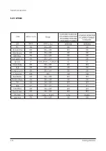
Page 23: ...3 ON ON ON ON ON ON OFF OFF OFF OFF ON OFF OFF OFF Large ON CT USA WIDE 4 3 ON ON ON ON ON ON OFF OFF OFF ON ON OFF OFF OFF Double ON CT USA WIDE 4 3 ON OFF ON OFF ON OFF ON OFF ON OFF ON OFF ON OFF O...

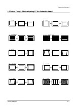
Page 24: ...and Adjustments Samsung Electronics 4 11 4 3 Screen Change When adjusting I2 C Bus Geometric items 8 PIN PHASE 10 V BOW 5 V ANGLE 4 PIN AMP 2 V LINEARITY 6 V SIZE 3 H SIZE 9 H SHIFT 7 V S CORRECTION...

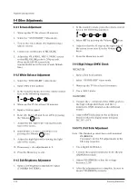
Page 25: ...djustments 6 9 11 Press the Menu key to exit 4 4 3 Sub Brightness Adjustment 1 Input a sub brightness adjustment signal TOSHIBA PATTERN 2 In the stand by mode press the remote control keys in the foll...

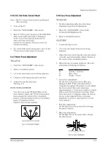
Page 26: ...t after the static focus adjustment and the tilt adjustment 2 Select the STANDARD video mode Contrast 100 Brightness 50 3 Input a crosshatch pattern ADJUSTMENT 1 Loosen the lens screws 2 Cover the two...

Page 27: ...il any light around the core disappears 11 Adjust G Focus so that the surrounding flash can disappear from the spot 12 After G Focus adjustments are complete adjust R Focus as above procedures 13 The...

Page 28: ...to a PWM type The existing type needs a capacity of about 6000P AC detect circuit eliminates unnecessary high frequency by using C476 D472 Also AC gain is limited to 0 7V D472 This AC gain is combine...

Page 29: ...unstable high voltage fluctuation the existing high voltage type REG circuit controls dynamic fluctuation by using C block capacitor But it can t detect actual dynamic fluctuation Also its velocity of...

Page 30: ...9 2 30 12 Y 440 28 2 64 6 42W5 DTV Mode X 932 Y 524 X 408 18 2 31 12 Y 488 40 2 68 6 22 19mm 73 97mm 3 3 3 5 mm 7 6 2 2 mm 2 2 1 9 mm 3 3 3 5 mm 41 12mm 70 81mm 4 2 9 5 mm 73 02mm 41 12mm 42 95mm 42W5...

Page 31: ...Alignment and Adjustments 4 18 Samsung Electronics 4 7 3 473W 4715W NORMAL MODE 4 7 4 473W 4715W DTV MODE...

Page 32: ...Alignment and Adjustments Samsung Electronics 4 19 4 7 5 5415R 545R 54J9 NORMAL MODE 4 7 6 5415R 545R 54J9 DTV MODE...

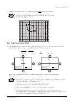
Page 33: ...Alignment and Adjustments 4 20 Samsung Electronics 4 7 7 552W 5515W 5525W 553W PTH5598 NORMAL MODE 4 7 8 552W 5515W 5525W 553W PTH5598 DTV MODE...

Page 34: ...Alignment and Adjustments Samsung Electronics 4 21 4 7 9 6215R NORMAL MODE 4 7 10 6215R DTV MODE...

Page 35: ...Alignment and Adjustments 4 22 Samsung Electronics 4 7 11 652W 653W 6515R NORMAL MODE 4 7 12 652W 653W 6515R DTV MODE...

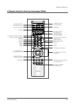
Page 36: ...Alignment and Adjustments Samsung Electronics 4 23 4 8 Remote Control for Servicing Convergence Mode...

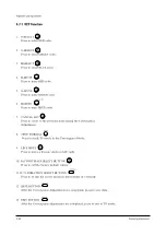
Page 37: ...ert to the previous data during the Convergence Adjustment 8 TEST NORMAL Press to check TV mode in the Convergence Mode 9 LINE SHIFT Press to move a line up down or left right 10 FACTORY DATA SELECT B...

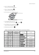
Page 38: ...65 653W 55 553W Model Name Representative Model 422W 4215W 42W5 4216W PCL545R PCL5415R PCL6215R HCL552W 5515W HCL652W 6515W HCL472W 4715W HCM653W HCM5525W 553W Basic Data Number after entring the Cg...

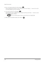
Page 39: ...n up down left right 21 Convergence Pattern Tilt Control Button After pressing the ANT A B button use the Channel Up Down and Volume buttons to create a tilt to the Convergence Pattern Note Use the fo...

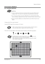
Page 40: ...ence adjustments correctly Otherwise any Perfect Focus error can happen 1 Warm up the TV for a least 30 minutes 2 Input an NTSC Signal Use an antenna or AV source Make sure that deflection yoke are pr...

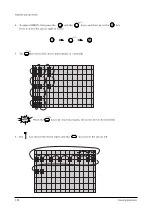
Page 41: ...t press the and the keys and then press the key Press to move the cursor right or down 5 The key moves the cursor horizontally or vertically When the key is pressed once again the cursor moves horizon...

Page 42: ...ignment and Adjustments Samsung Electronics 4 29 7 Use the key for overall balance 8 After the Line Shift is cancelled by pressing the key use the Channel and Volume keys Up Down to make big adjustmen...

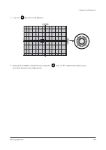
Page 43: ...colors by pessing the and the keys 11 To adjust RED redo steps 5 7 When the cursor moves vertically 12 To superimpose the blue and green colors press 1 the key for R Mute 2 the key to cancel the B Mut...

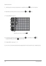
Page 44: ...Auto Covergence is porformed in the following sequences G R B Up Down Left Right When auto Convergence is complete the data is automatically saved and the convergence pattern revets w After Factory A...

Page 45: ...rgence adjustment must be done same as the above Normal Mode Convergence Adjustment Use a 16 9 screen jig for DTV When Convergence Adjustment is not normally done or the convergence center is misalign...

Page 46: ...SCAN 1 PROTECT PORT GND REMOCON INPUT POWER ON OFF RELAY CONTROL SCL1 SERIAL CLOCK LINE 1 SDA1 SOUND RESET STANDY BY LED RESET SERIAL DATA LINE 1 1 03 V TIMER LED TIMER LED 2 07 V 1080 i 1080i MODE SW...

Page 47: ...ORIZONTAL BLANK VERTICAL BLANK GND N C GND GND TTX CVBS GND GND SUB TUNER SWITCH 2 TTX CAPTION CVBS VS1 VERTICAL SYNC N C N C 215 51 mV 3 74 V 3 26 V 168 mV 0 46 V 0 46 V 7 31 mV HS1 HORIZONTAL SYNC N...

Page 48: ...15 93 mV GND EAST WEST OUT VERTICAL BLANK VERTICAL DRIVE VOLTAGE HORIZONTAL DRIVE GND V RESET VIDEO SIGNAL MUTE SCL1 SERIAL DATA LINE HORIZONTAL SYNC VERTICLA OUT SERIAL CLOCK LINE OSD TTX FB OSD TTX...

Page 49: ...P Y C CVBS 5 V DW1 VM Y OUTPUT SW2 CONTROL PIP C INPUT PIP Y CVBS INPUT GND GND GND RF1 CVBS DVD Pr R COMPONENT1 DVD Y G COMPONENT1 GND 1 33 mV GND GND MAIN C MAIN C INPUT 1 34 mV 1 57 mV 4 89 V MAIN...

Page 50: ...ONVERGENCE RED 0 27 mV 10 CG G CONVERGENCE GREEN 0 26 mV 0 29 mV 3 5 V 3 7 V 88 95 mV 34 27 mV 107 32 mV 101 52 mV 15 83 mV 104 32 mV 5 24 V 275 mV 13 22 mV 4 99 V 11 CG B CONVERGENCE BLUE 12 SDA1 SER...

Page 51: ...MEMO 4 38 Samsung Electronics...

Page 52: ...rd Replace FD101S FD102S and check associate circuits Check the circuits related to ICZ103 ICZ104 Check the circuits related to CNZ02 CNZ04 CNZ05 Check DY Check the input output of ICZ103 ICZ104 on th...

Page 53: ...e level of MAIN CN601 Check SPEAKER Check ICD603 Abnomal Abnomal Abnomal Abnomal Abnomal Nomal Nomal Nomal Nomal Nomal Check the circuits related to IC601 Check IC602 Check the circuits related to IC6...

Page 54: ...2 Check the input voltage of PWE CORD Check MICOM VCC Check the input voltage Check IC831 PC801S Check QS802 Check ICS801 PC811S Check the voltage waveform of CN801 CN802 CN401 Check the output from D...

Page 55: ...MEMO 5 4 Samsung Electronics...

Page 56: ...BP91 00906B ASSY PRT HCN5529WX XAA P58A 1 A PRT 14 AA60 00072B SPACER COVER DUST 43 54 62J9 SPONGE V0 9 1 SCDUST 15 AA67 00206A MIRROR FRONT 55W9 FSM 1027 799 540 1 MF 16 BP61 00032A BRACKET F MIRROR...

Page 57: ...ASSY COVER P DOOR RACK DP BP64 00154A 54 1 ADRACK 14 6002 000522 SCREW TAPPING TH 2 M4 L15 ZP 3 15 BP96 00226C ASSY COVER P WOOD 54T8 WOOD SEA 1 A CW 16 BP94 00445M ASSY PCB MAIN ST54T8PCX XAX P55A 17...

Page 58: ...RAMIC DISC 4 7NF 100 0 5 5 CZ105 2201 000516 C CERAMIC DISC 4 7NF 100 0 5 5 CZ110 2201 000604 C CERAMIC DISC 56PF 100 0 50 5 CZ111 2401 000480 C AL 10UF 20 50V GP 5X11MM 5M 5 CZ112 2401 000832 C AL 22...

Page 59: ...C312 2203 000181 C CERAMIC CHIP 100nF 80 20 25V Y5V TP 5 DC313 2203 000181 C CERAMIC CHIP 100nF 80 20 25V Y5V TP 5 DC401 2203 000181 C CERAMIC CHIP 100nF 80 20 25V Y5V TP 5 DC403 2203 000181 C CERAMIC...

Page 60: ...EAKER 30W 8ohm 96dB 60Hz 3 L SPK1 AA39 00042B LEAD CONNECTOR ASSY 2 7UF REC REC 300MM 3 CAS CW AA60 10051A SCREW WOOD PH M4 L16 ZPC BLK SWRCH18A 3 FOOT CW AA60 10051A SCREW WOOD PH M4 L16 ZPC BLK SWRC...

Page 61: ...AMIC CHIP 100nF 80 20 25V Y5V TP 4 DC401 2203 000181 C CERAMIC CHIP 100nF 80 20 25V Y5V TP 4 DC403 2203 000181 C CERAMIC CHIP 100nF 80 20 25V Y5V TP 4 DC405 2203 000181 C CERAMIC CHIP 100nF 80 20 25V...

Page 62: ...A DEFLECTION YOKE DPD 5292AA S S 7 29 1 3 CY AA33 00016A MAGNET CONVERGENCE JH 92LT 29F 29 1M 3 L CONN AA39 00018A LEAD CONNECTOR ASSY YFH800 01 YRH187RH 3 H DY BP61 00079A HOLDER DY PJTV T0 5 NYLON66...

Page 63: ...5 CZ152 2202 000121 C CERAMIC MLC AXIAL 100pF 10 50V Y5P TP 5 CZ153 2202 000121 C CERAMIC MLC AXIAL 100pF 10 50V Y5P TP 5 CZ154 2202 000121 C CERAMIC MLC AXIAL 100pF 10 50V Y5P TP 5 CZ155 2202 000121...

Page 64: ...5 Q561 0502 000006 TR POWER KSC1507 NPN 15W TO 220 TP 120 5 R504 2001 000006 R CARBON 2 4Kohm 5 1 8W AA TP 1 8x3 2m 5 R556 2001 000007 R CARBON 3KOHM 5 1 8W AA TP 1 5 R516 2001 000009 R CARBON 20KOHM...

Page 65: ...PPER TA0 6SN 52M M A 5 J561 3812 000219 JUMPER WIRE SO COPPER TA0 6SN 52M M A 5 J565 3812 000219 JUMPER WIRE SO COPPER TA0 6SN 52M M A 5 J566 3812 000219 JUMPER WIRE SO COPPER TA0 6SN 52M M A 5 J568 3...

Page 66: ...6T 24 5 D01 BP32 00001A SENSOR PHOTO BCS5030G1 40 TO 85 0 42 U 2 D B AA26 00101A TRANS FBT FWZ50A001E 2 C WIRE AA65 30018A CLAMP WIRE NYLON6 6 DATL 2 PCB CPAC AA65 30104B CLAMP WIRE NYLON 66 V2 BLK W...

Page 67: ...CS XAX P55A 3 SILGRY 0201 001030 ADHESIVE SIL SE9178 GRY NON FLOW UL94V0 3 TAPE AC 0203 001303 TAPE ACETATE 1554 T0 25 W19 L30000 WHT 3 GLYCOL 0204 001148 ETHYLENE GLYCOL MS S02 CH20HCH20H 80 20 3 CRT...

Page 68: ...00577F ASSY ACCESSORY ST54T8PCS XAX P55A 2 BATT 4301 000121 BATTERY MN 1 5V AAA 10 5X44 2 C RCA AA39 00006A CABLE RCA RCA 3000MM 0 12 10 RED WHT Y 2 RMT AA59 00262A REMOCON TM63 COMMONDO 48 G6671B EX...

Page 69: ...7 12 Samsung Electronics MEMO...

Page 70: ...80 mA 219 mA 29 mA 293 mA 14 mA 138 mA 154mA 90m 380 mA 640 mA 15 mA 1500 mA 730 mA 745 mA 780 mA 975 mA 1 5 A Micom Eeprom SI 3050C 5 3V KA278RA05 A 5 3V KA278RA05 A 5 3V High Volt Deflection VM 117V...

Page 71: ...5A 20V 0 75A 13 5V 0 78A 20V 0 73A HOT PC PS2561 SE110 AC IN COLD Line Filter 1mH 5A Line Filter 1mH 5A Line Filter 10mH 5A Line Filter 10mH 5A INPUT RECTFIER RBV 606 Switching IC STR X6456 FUSE 7V 0...

Page 72: ...12V 20V 20V 20V 20V 5 0V 5 0V 117V 117V 0 98A 13 5V 0 78A 20V 0 7A 20V 0 75A 8 0V 1 5A POWER Trans Dummy Trans HV Control HV HDT HV OUT PUT FBT CRT Drive Horizantal Conv Amp Vertical Conv Amp Horizant...

Page 73: ...agrams 8 4 Samsung Electronics 8 4 SDC Perfect Focus Block Diagram Up Sensor Left Sensor Right Sensor Down Sensor AMP LPF MUX ADC SDC12 Cg MICOM Pattern Generator SDC12 Convergence Control SDC12 AMP L...

Page 74: ...7 18 19 22 21 23 24 25 26 27 28 1 2 3 4 5 6 7 8 9 10 11 12 13 14 TV L1 MONITOR L2 SCART1 L3 SCART2 VIDEO2 L4 SCART3 VIDEO1 L5 AV4 VIDEO3 L6 TV R1 SCART3 VIDEO1 R5 SCART2 VIDEO2 R4 SCART2 R3 MONITOR R2...

Page 75: ...IN AV1 L IN AV2 R IN AV2 L IN AV3 R IN AV3 L IN AV4 R IN AV4 L IN EXT L EXR R DTV2 R DTV2 L DTV1 R DTV1 L MAIN TUNER DACA R OUT DACA L OUT MAIN R OUT MAIN L OUT CENTER OUT SURROUND OUT SC2 OUT_R SC2 O...

Page 76: ...S Main CVBS Sub CVBS SDA SCL RF2 CVBS MAIN Y CVBS VCC VCC VCC 9407 Scanrate Converter BOh Input MAIN 656100 656107 Digital Signal Y Cb Cr H V Cb Cr H V Cb Cr H V 3 5 1 12 24 Sync Counter Comp Switchin...

Page 77: ...ER 15 COMP 13 STD BY5V 12 GND 11 HD 10 GND 9 PROTECT 8 EW 7 VD 6 VD 5 ABL 4 1080i 3 V BLK 2 GND 1 H BLK CONV AMP H1 H2 V1 V2 CY R G B 4P X 3 DY R G B 4P X 3 4P X 1 DY JACKC CONNECTION H1 H2 V1 V2 S I...

Page 78: ...TP02 TP01 10 Schematic Diagrams Samsung Electronics Schematic Diagrams 10 1 10 1 MAIN 1 TP01 TP02...

Page 79: ...Schematic Diagrams 10 2 Samsung Electronics TP20 TP03 TP04 10 2 MAIN 2 TP03 TP04 TP20...

Page 80: ...Samsung Electronics Schematic Diagrams 10 3 10 3 MAIN 3 TP12 TP13 TP12 TP13...

Page 81: ...Schematic Diagrams 10 4 Samsung Electronics 10 4 MAIN 4 TP10 TP11 TP09 TP08 TP07 TP06 TP05 TP19 TP18 TP17 TP16 TP14 TP15 TP05 TP06 TP07 TP08 TP09 TP10 TP19 TP18 TP17 TP16 TP15 TP14 TP11...

Page 82: ...Samsung Electronics Schematic Diagrams 10 5 10 5 MICOM...

Page 83: ...Schematic Diagrams 10 6 Samsung Electronics 10 6 CRT...

Page 84: ...Samsung Electronics Schematic Diagrams 10 7 10 7 SUB 1 TP21 TP21...

Page 85: ...Schematic Diagrams 10 8 Samsung Electronics 10 8 SUB 2 TP24 TP23 TP22 TP22 TP23 TP24...

Page 86: ...Samsung Electronics Schematic Diagrams 10 9 10 9 CONVERGENCE SDC12 1...

Page 87: ...Schematic Diagrams 10 10 Samsung Electronics 10 10 CONVERGENCE SDC12 2...

Page 88: ...Samsung Electronics Schematic Diagrams 10 11 10 11 PRO SCAN 1...

Page 89: ...Schematic Diagrams 10 12 Samsung Electronics 10 12 PRO SCAN 2...

Page 90: ...Samsung Electronics Schematic Diagrams 10 13 10 13 PRO SCAN 3...

Page 91: ...Schematic Diagrams 10 14 Samsung Electronics 10 14 PRO SCAN 4...

Page 92: ...10 15 CG AMP Samsung Electronics Schematic Diagrams 10 15...

Page 93: ...Schematic Diagrams 10 16 Samsung Electronics 10 16 AV FRONT...

Page 94: ...10 17 CONTROL Samsung Electronics Schematic Diagrams 10 17...

Page 95: ...Schematic Diagrams 10 18 Samsung Electronics 10 18 DY JACK SENSOR DY JACK SENSOR...

Page 96: ...Electronics Co Ltd JUL 2003 Printed in Korea AA82 00798A This Service Manual is a property of Samsung Electronics Co Ltd Any unauthorized use of Manual can be punished under applicable International...

Reviews: