


10 Operating Instructions and Installation
10-3
1. Connecting an Aerial or Cable Television Network
To view television channels correctly, a signal must be received by the set from one of the following sources:
- An outdoor aerial / A cable television network / A satellite network
2. Connecting HDMI/DVI
- Supports connections between HDMI-connection-enabled AV devices
(Set-Top Boxes, DVD players, AV receivers and digital TVs).
- No sound connection is needed for an HDMI to HDMI connection.
> What is HDMI?
- HDMI, or high-definition multimedia interface, is a next-generation interface that enables the transmission of digital
audio and video signals using a single cable without compression.
- "Multimedia interface" is a more accurate name for it especially because it allows multiple channels of digital
audio (5.1 channels).The difference between HDMI and DVI is that the HDMI device is smaller in size, has the
HDCP (High Bandwidth Digital Copy Protection) coding feature installed, and supports multi - channel digital
audio.
- Use the HDMI/DVI terminal for DVI connection to an extended device.
> You should use the DVI-to-HDMI cable or DVI-HDMI Adapter for the connection, and the "R - AUDIO - L"
terminal on DVI for sound output. - When connecting this product via HDMI or DVI to a Set Top Box, DVD Player
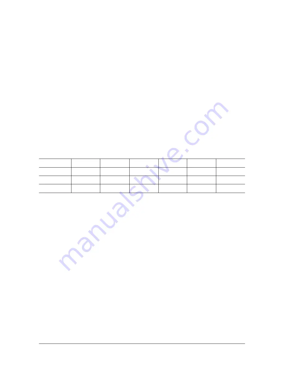
or Games Console etc, make sure that it has been set to a compatible video output mode as shown in the table
below. Failure to observe this may result in picture distortion, image breakup or no picture.
> Supported modes for DVI or HDMI
- Do not attempt to connect the HDMI/DVI connector to a PC or Laptop Graphics Card.
(This will result in a blank screen being displayed)
3. Connecting Component Devices (DTV/DVD)
- Connect component video cables (optional) to component connector ("PR", "PB", "Y") on the rear of your set and
the other ends to corresponding component video out connectors on the DTV or DVD.
- If you wish to connect both the Set-Top Box and DTV (or DVD), you should connect the Set-Top Box to the DTV (or
DVD) and connect the DTV (or DVD) to component connector ("PR", "PB", "Y") on your set.
- The PR, PB and Y connectors on your component devices (DTV or DVD) are sometimes labeled Y, B-Y and R-Y or
Y, Cb and Cr. - Connect RCA audio cables (optional) to "R - AUDIO - L" on the rear of your set and the other ends
to corresponding audio out connectors on the DTV or DVD.
- This LCD TV displays the optimum picture in 720p mode.
- This LCD TV displays the maximum picture in 1080i mode.
5. Connecting External A/V Devices (AV IN 2)
- Connect RCA or S-VIDEO cable to an appropriate external A/V device such as VCR, DVD or Camcorder.
- Connect RCA audio cables to ¡°R - AUDIO - L¡± on the rear of your set and the other ends to corresponding audio
out connectors on the A/V device.
- Headphone may be connected to the headphone output (4) on the rear of your set. While the headphone is con
nected, the sound from the built-in speakers will be disabled.
6. SERVICE
- Connector for engineer.
7. Connecting AUDIO
- Connect RCA audio cables to ¡°R - AUDIO - L¡± on the rear of your set and the other ends to corresponding audio
in connectors on the Amplifier or DVD Home Theater.
50Hz
480i
X
X
X
X
X
O
O
O
O
O
O
O
O
O
O
O
O
O
480p
576i
576p
720p
1080i
60Hz
Component
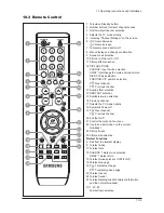
Summary of Contents for GBD26KS
Page 2: ... 豪华超薄设计 超级画质 超级音质 极其舒适 使用方便 ...
Page 7: ...Memo 1 Precautions 1 4 ...
Page 11: ... _ _ _ _ ab ab ab ab c c c c IJ Id MN U ...
Page 22: ... ...
Page 23: ... 0 1234453 6789 AB CDEF GHIJ GK GK GK GK GLCM 1NOPQ RSTUV WXYZ LC YZ 23 _ ...
Page 27: ... F F F F º D D D D wx ny gh t t t I 0 9 0 9 B EF EF CDEF 4 4 PQ PQ PQ PQ L ...
Page 28: ... L L 6 À Á cd 8 8 8 à 8 8 8 ...
Page 30: ...10 2 Connection Panel 10 Operating Instructions and Installation 10 2 ...
Page 35: ... 0123 45 6789 ABCDEFGHI JIK LM N O PQR LST O PQR ...
Page 36: ... UVMNW OST LSTXY OQR WUVSTXY ...
Page 37: ... LZI O LZI OQR WUVZI ...
Page 38: ... L OQR LAZXY OQR UVAZXY ...
Page 39: ... UV _AZ ab ...
Page 40: ... ...
Page 44: ... ...
Page 45: ... ...
Page 46: ... ...
Page 47: ... ...
Page 48: ... ...
Page 51: ... g Þ Õ Ì W L N0 õö k kü ...
Page 52: ... y UV e J V y h e G y UV h e ...
Page 55: ...13 Circuit Descriptions 13 3 13 2 Main Block ...
Page 56: ...13 Circuit Descriptions 13 4 13 3 SMPS Board 13 3 1 26 32 SMPS Block 13 3 2 26 32 SMPS Block ...
Page 57: ...13 Circuit Descriptions 13 5 13 3 3 26 32 SMPS Block 13 3 4 26 32 SMPS Block ...
Page 58: ...13 Circuit Descriptions 13 6 ...
Page 59: ...13 Circuit Descriptions 13 7 13 3 5 32 40 IP Board 13 3 6 32 40 IP Board ...
Page 60: ...Memo 13 Circuit Descriptions 13 8 ...
Page 61: ... ...
Page 62: ... 0 1 0 1 0 1 2345 1 ...
Page 63: ... 67 89 ABC D EFG6 H I 1 8 JKJL1 ...
Page 64: ...4 Troubleshooting 4 4 WAVEFORMS 1 R G B Output Signal of IC500 ...
Page 65: ... 67 89 ABC D EFG6 H JKJ L1 8 M JKJL1 ...
Page 66: ...4 Troubleshooting 4 6 2 Digital Output Data of IC500 3 Signal of HDMI Data ...
Page 67: ... 67 N OPQ ABC D EFG6 H 1 1 8 M JKJL1 RS I RS ...
Page 68: ...4 Troubleshooting 4 8 WAVEFORMS 4 Tuner_CVBS Output Signal 3 CVBS Output Signal ...
Page 69: ... 67 TU V ABC D EFG6 H 1 8 M JKJL1 WS ...
Page 70: ...4 Troubleshooting 4 10 WAVEFORMS 4 CVBS Output Signal ...
Page 71: ... 67 V ABC D EFG6 H 1 8 M JKJL 1 XYZ 4 ...
Page 72: ...4 Troubleshooting 4 12 2 Digital Output Data of IC500 5 Analog Signal Y C to IC500 WAVEFORMS ...
Page 73: ... TU N OPQ 1 1 _ Q RS I RS ...
Page 74: ...4 Troubleshooting 4 14 WAVEFORMS 6 The Signal are Inputed to IC603 7 DC 12V ...
Page 150: ...7 Block Diagrams 7 2 Memo ...
Page 151: ...12 PCB Diagram 12 1 12 PCB Diagram 12 1 26 Main PCB Diagram ...
Page 153: ...12 PCB Diagram 12 3 12 3 26 SMPS board ...
Page 154: ...12 PCB Diagram 12 4 12 4 32 SMPS board ...
Page 155: ...12 PCB Diagram 12 5 12 5 40 IP Board ...
Page 156: ...12 PCB Diagram 12 6 Memo ...
Page 157: ...8 1 8 Wiring Diagrams 8 Wiring Diagram 8 1 LA26R71B LA32R71B LA40R71B Wiring Diagram ...
Page 158: ...8 Wiring Diagrams 8 2 8 2 Main Board Layout ...
Page 161: ...8 5 8 Wiring Diagrams ...
Page 162: ...8 Wiring Diagrams 8 6 8 4 Power Board Layout ...
Page 165: ...8 9 8 Wiring Diagrams ...
Page 168: ...8 Wiring Diagrams 8 12 Memo ...
Page 169: ... ...
Page 170: ... ...
Page 171: ... ...
Page 172: ... ...
Page 173: ... ...
Page 174: ... ...
Page 175: ... 01 23 45 6 78 9 A BC DE FGH I ...


