


CNF24 User Guide
© SAMSUNG Electronics Co., Ltd.
11
Front View of CNF24
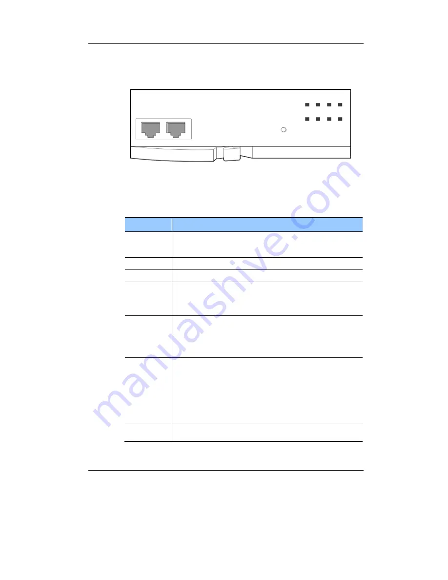
The front view of the CNF24 is shown in the figure below:
Figure 1.1 Front View of the CNF24
The components on the front panel of the CNF24 are listed in Table 1.1.
Table 1.1 Ports and LEDs of the CNF24
Ports, LEDs
Functions
LAN
Ethernet port that connects to the LAN.
- Connector: RJ45
- Cable: CAT 5 cable, UTP
SIO
UART port (for tests).
RST
Button for resetting the CNF24.
RUN LED
This LED indicates CNF24 status.
- Off: Power is not being supplied.
- On: Booting.
- Blink: The RAM program is operating.
SVC LED
This LED indicates if the CNF24 service is available.
This LED turns on when the CNF24 software task can be
accessed.
- Red blink: CNF24 service is not available
- Green blink: CNF24 service available
LAN LED
This LED indicates the status of the Ethernet link
- Red: Linked as 10 BASE-T Ethernet mode
- Red blink: Transmitting/receiving data as 10 BASE-T
- Green: Linked as 100 BASE-T Ethernet mode
- Green blink: Transmitting/receiving data as 100 BASE-T
- Orange: Linked as 1000 BASE-TX Ethernet mode
- Orange blink: Transmitting/receiving data as 1000 BASE-TX
- Off: Link off
MC LED
- Green blink: Auxiliary memory (NAND) is accessed.
- Off: No access
RST
CNF24
LAN
SIO
RUN SVC LAN
CONF
MC
REC MEM
BACKUP
Summary of Contents for CNF24
Page 1: ...Ed 00 CNF24 User Guide ...
Page 15: ...CNF24 User Guide SAMSUNG Electronics Co Ltd 15 This page is intentionally left blank ...
Page 21: ...CNF24 User Guide SAMSUNG Electronics Co Ltd 21 This page is intentionally left blank ...
Page 43: ...CNF24 User Guide SAMSUNG Electronics Co Ltd 43 Figure 4 1 Conference Options ...