background image

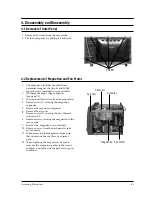
1. Disconnect the oven from the power source.
2. Remove the 10A fuse from the fuse holder.
3. When replacing the 10A fuse, use an exact

replacement and check the primary interlock ,
door sensing  and interlock monitor switches.

4.  When the above switches operate properly,

check that the control circuit transformer is not
defective.

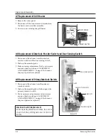
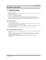
1. Be sure to disclyarge any static electricity from

your body, and avoid touching the "Touch
control" clrcuitry.

2. Disconnect  the connectors from the control

circuit board.

3. Remove screws 

¥L

and

¥M

securing the control

circuit bord.

4. Lift up the control circuit board from right side

and remove the hooks holding the contol
circuit board to the box assembly.

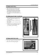
1. Disconnect  all lead wires from the gas sensor.
2. Remove screws securing the air guide.

4-10 Replacement  of Fuse

Samsung Electronics

4-5

4-11 Replacement of Control  Circuit Board

4-12 Replacement of Gas Sensor

Disassembly and Reassembly

Screw

¥L

Screw

¥M

Gas sensor

Screw

Summary of Contents for CE1279KSE

Page 1: ...OWAVE OVEN CONTENTS 1 Precautions 2 Specifications 3 Operating Instructions 4 Disassembly and Reassembly 5 Alignment and Adjustments 6 Circuit Description 7 Troubleshooting 8 Exploded Views and Parts List 9 PCB Diagrams 10 Schematic Diagrams BWT ...

Page 2: ...ce test or inspection within the microwave generating compartments check the magnetron wave guide or transmission line and cavity for proper alignment integrity and connections d Any defective or misadjusted components in the interlock monitor door seal and microwave generation and transmission systems shall be repaired replaced or adjusted by procedures described in this manual before the oven is...

Page 3: ... only the exact replacements for the following parts Primary and secondary interlock switches interlock monitor switch 12 If the fuse is blown by the Interlock Monitor Switch Replace all of the following at the same time Primary and secondary switches as well as the Interlock Monitor Switch The correct adjustment of these switches is described elsewhere in this manual Make sure that the fuse has t...

Page 4: ...her hazards 1 High Voltage Warning Do not attempt to measureany of the high voltages this includes the filament voltage of the magnetron High voltage is present during any cook cycle Before touching any components or wiring always unplug the oven and discharge the high voltage capacitor See Figure 1 1 2 The high voltage capacitor remains charged for about 30 seconds after disconnection Short the n...

Page 5: ...S COOLING METHOD COOLING FAN MOTOR OUTSIDE DIMENSIONS 547 W x 352 H x 516 D POWER LEVEL CE1279KSE 10 85W 4 sec 26 sec 20 170W 7 sec 23 sec 30 255W 10 sec 20 sec 40 340W 13 sec 17 sec 50 425W 16 sec 14 sec 60 510W 19 sec 11 sec 70 595W 22 sec 8 sec 80 680W 25 sec 5 sec 90 765W 28 sec 2 sec 100 850W 30 sec 0 sec ON TIME OFF TIME 2 2 Comparison Chart MODEL FEATURE MORE LESS AUTO COOK DISH AUTO DEFROS...

Page 6: ...LL MW OVEN STOP CANCEL More Less Power Level dish 3 Operating Instructions 3 1 Control Panel Samsung Electronics 3 1 3 2 Features External Views DOOR LATCHES DOOR LIGHT HEATER DISPLAY CONTROL PANEL INHALATION SLOT GUIDE ROLLER VENTILATION HOLES CERAMIC TRAY SAFETY INTERLOCK HOLES ...

Page 7: ...7 Remove screw 1 securing the assy thermal cutout switch 8 Remove screws securing the magnetron to the wave guide 9 Remove the magnetron very carefully 10 Remove screws from the back panel to take out fan motor 11 When removing the magnetron make sure that its antenna does not hit any adjacent parts 12 When replacing the magnetron be sure to remount the magnetron gasket in the correct position and...

Page 8: ...onnect the leads securely 1 Remove bolts securing the upper hinge and lower hinge then remove the door assmbly 2 After replacing the door check the operation of the primary interlock switch and the interlock monitor switch 3 Microwave emission should not exceed 5 All service adjustments should be made for minimum RF emission Disassembly and Reassembly H V TRANS H V FUSE HINGE UPPER HINGE VOLT HING...

Page 9: ... Remove screws securing the elevation motor to the cavity 6 Remove the elevation motor 7 When replacing the elevation motor be sure to remount it in the correct position 8 Reconnect all the leads to the elevation motor 9 Screw the elevation motor cover to the base plate with screw driver 10 Remount the coupler in the correct position 4 6 Replacement of Elevation Motor Disassembly and Reassembly EL...

Page 10: ...ch 2 Push up the mounting tabs which support the primary interlock switch 3 Make necessary adjustments and microwave emision check according to ALIGNMENT AND ADJUSTMENTS on page 5 2 whenever they are repaired or replaced 4 7 Replacement of Grill Heater 4 8 Replacement of Interlock Monitor Switch and Door Sensing Switch 4 9 Replacement of Primay Interlock Switch 4 4 Samsung Electronics Disassembly ...

Page 11: ...rom your body and avoid touching the Touch control clrcuitry 2 Disconnect the connectors from the control circuit board 3 Remove screws L and Msecuring the control circuit bord 4 Lift up the control circuit board from right side and remove the hooks holding the contol circuit board to the box assembly 1 Disconnect all lead wires from the gas sensor 2 Remove screws securing the air guide 4 10 Repla...

Page 12: ...motor assembly 4 Adjustment or exchange 5 Reconnect all the lead wires 1 Remove screw 1 securing the sensor thermister 2 Disconnect all lead wires from the mian wire 4 13 Replacement of Back cover and Oven motor assembly 4 14 Replacement of Sensor Thermister Disassembly and Reassembly SCREW Sensor thermister Back cover screws Oven motor Assembly ...

Page 13: ...ent terminal and the magnetron case should read open 1 The low voltage transformer is located on the base plate 2 Remove the low voltage transformer from the base plate and check continuity 3 Normal resistor readings a shown in the table PRECAUTION 1 High voltage is present at the high voltage terminals during any cook cycle 2 Do not attempt to measurement the high voltage 3 Before touching any ov...

Page 14: ... to the oven assembly adjust the Latch Body by moving it so that the oven door has vo play Check for play by pulling the door assembly Make sure that the latch keys move smoothly after adjustment is completed Completely tighten the screws holding the latch body to the oven assembly 4 Reconnect to Monitor switch and re check that the the monitor circuit and all latch switches are secured see compon...

Page 15: ... in the temperature rise Additional power test should be done if temperature rise is marginal NOTE 2 Output power in watts is computed by multiplying the temperature rise step E by a factor of 91 times the centigrade temperature The microwave heat distribution can be checked indirectly by measuring the water temperature rise at certain positions in the oven 1 Prepare five beakers made of Pyrex eac...

Page 16: ...t survey meter dual ranges to 2 450MHz 4 When measuring the leakage always use the 2 inch spacer cone with the probe Hold the probe perpendicular to the cabinet door Place the spacer cone on the door seam and move the probe along the viewing windows and exhaust openings Move the probe at about 1 inch per second If the leakage from door seam is measured near a corner keep the probe perpendicular ma...

Page 17: ...exceed the limited scale 2 The test probe must be held on the grip of the handle otherwise a false reading may result when the operator s hand is between the handle and the probe 3 When high leakage is suspected do not move the probe horizontally along the oven surface this may cause damage to the probe 4 Follow the recommendation of the manufacturer of the microwave energy survey meter 5 9 5 Reco...

Page 18: ...ransformer This 3 4V is applied to the magnetron to heat the magnetron filament through two noise preventing choke coils 6 High voltage 2 230 volts AC is generated by the high voltage transformer secondary This secondary voltage is increased by the diode and high voltage capacitor This resultant DC voltage is then applied to the anode of the magnetron As shown in Fig 2 the first half cycle of the ...

Page 19: ...rimary interlock switch open and the contacts of interlock monitor switch close 5 If the contacts of primary interlock switch do not function properly the monitor fuse blows out because of the large current surge caused by the monitor switch activation which stops magnetron oscillation see Fig 3 6 5 When the CANCEL pad is touched during cooking 1 Touching the CANCEL pad once stops cooking Touching...

Page 20: ...s including the dish it swings once and then cookis in the basic location If the weight is 700g the cooking is done in the basic location 4 Manual cooking is done in the basic location with only the rotating motor operating 7 1 3 Operating Principle of the Height Sensor The weight sensor converts the weight of the food into a series of pulses that are compared to the zero point wavefrom This frequ...

Page 21: ...l reading is between 0350 and 0650 8 Press the cancel key to complete the adjustment 7 1 5 Error codes Error indication Cause of occurrence Management method Remarks E0 Gas sensor open short Check the connection and Automatic sensor value cooking reheating reheating between 6 and 211 Put the power switch again and and use it after 10 minutes E1 Exceeds of T1 time limit First press the cancel key a...

Page 22: ...g dish Putting food that exceeds 4kg Total can damage the weight sensor 2 Use only genuine replacements that fit the model C E rotating dish and supporter 3 When food exceeding 300g Total is put on the rotating dish the oven operates for only 10 minutes Error E6 7 1 8 Reparing Parts 1 Discharge the capacitor for about 5 to 6 minutes after cutting the power and then continue the work 2 Do not damag...

Page 23: ...G 5 DO NOT TOUCH ANY PART OF THE CIRCUIT OR THE CONTROL CIRCUIT BOARD SINCE STATIC DISCHARGE MAY DAMAGE IT ALWAYS TOUCH GROUND WHILE WORKING ON IT TO DISCHARGE ANY STATIC CHARGE BUILT UP Item Checking Procedwre Inspection of a Put about 200cc of tap water water temperature 10 18 on microwave oven cooking the rotating dish b Do the following Microwave oven high time setting 5 minute start cooking c...

Page 24: ...d poor Exchange c Monitor switch short switch Poor operation Latch adjustment d HVC Short circuit Exchange e Latch operation Poor operation Latch adjustment Problem location Cause Measures Electrical a Grounding wire Bad grounding Inspection shock b AC 230V power line is Lead wire not connected the chassis Exposed part of the power Adjustment line is shorting the chassis Lamp is not on a Lamp and ...

Page 25: ...n c Piacement of the bupporter Poor placement of and adjustment rotating shaft Microwdve leakage a Condition of the door Assembly Not enough contact Adjust the door puring operation b The surface contacting the in the front side of the hinge front of the cooking room and cooking room and the Checktheoperating the door door condition of the Deformation safety switch Adjustment or exchange Food does...

Page 26: ...djustment c Alien substance in the motor Fan motor a Continuity between terminals Disconnection Exchange doesn t rotate Measure after disconnecting the Poor insertion and Adjustment power and lead wire disconnection b Lead terminal Bad contacts needs Adjustment c Rotate the fan by hand cleaning or exchange Poor defrosting a Check the connections to Poor connection Adjustment the weight sensor b Re...

Page 27: ...ction switch 3 Applicability of parts Check that exact replacement parts are being used AC 230V 4 Placement of Check for looseness jamming or terminal insertion lead wire of the lead wire check that there are no shorts to ground 5 Connection of Check the connection between he screw and bolt screw and bolt 6 Alien substance Check for a cut line within the equipment insertion check combustible forei...

Page 28: ...1 Exploded Views 8 1 47 NC NO COM NC NO COM 1 2 3 27 28 29 29 32 33 34 35 37 38 41 43 45 39 40 44 62 51 21 22 58 59 48 46 36 42 61 55 54 56 57 71 72 73 74 49 50 67 68 63 46 6 8 7 9 10 18 17 15 14 23 31 19 20 13 24 25 16 11 12 52 53 64 4 5 65 66 69 70 26 30 ...

Page 29: ... L275 BLK 1 23 DE39 40683A WIRE HARNESS A 230V50HZ CE1279KSE RUSSIA 1 24 DE63 90062A CUSHION RUBBER DOOR RUBBER CR T9 W30 L50 RE 1300 1 25 DE61 30132A SUPPORTER MGT SECC T0 6 W38 L342 5 MW6630T 1 26 DE91 70101B ASSY THERMOSTAT RE 542 160 60 187TYPE 1 27 DE47 20007A THERMOSTAT PW 2N 160 60 187Z 250V7 5A 160 1 28 DE61 50490A BRACKET TCO SECC1 T0 6 34 58 1 29 DE03 30035A MAGNETRON OM75PH 31 ESS 1 29 ...

Page 30: ... K2 1 59 DE72 60035L GUIDE AIR SECC T 0 6 W 240 L 242 5 RE 1 61 DE92 40001P ASSY DOOR CE1279KSE SBTW WHT HANDLE 1 62 DE92 90018B ASSY TRAY SUB STS304 RE 751 652 1 63 DE74 20045A TRAY CERAMIC RE 909CG 1 64 DE74 20107A TRAY BROILER SPP O 8T 345 345 345 ENAMEL SI 1 65 DE74 20022A TRAY OIL GLASS NEOREX T5 PI210 600G 1 66 DE92 90334A ASSY LEG M9GF45 1 67 DE92 90433A ASSY SHAFT BARBECUE CE979GSE STS304 ...

Page 31: ... SELANT BLK 1 5 DE64 40173A DOOR C PBT BLK 24G RE 1300 1 6 DE64 20024A HANDLE DOOR PC BLK 89G RE 751 652 1 7 DE64 40175A DOOR KEY POM TC3005 BLK 13G RE 330 1 8 DE61 70041B SPRING KEY ES HSW3 PI0 7 D4 9 BLUING RE 7 1 9 DE60 60073A PIN HINGE MOLD 4 17 5 2 10 DE68 10001A LABEL BRAND AL SAMSUNG S S 8 0 50 1 11 DE61 80037C HINGE UPPER SCP1 T3 0 W26 L76 ZP2C W MB245 1 12 DE61 80006B HINGE LOWER ZP2W T3 ...

Page 32: ...3 DE92 90443C ASSY BUTTON START CE979GSE CIS 1 4 DE91 10497A ASSY P C B MAIN RC 753 02 230V50HZ VFD CE1279 1 5 DE64 10049A KNOB COVER ABS NTR 9G RE 642 1 6 DE66 20071A BUTTON SELECT E ABS NTR 20G RE 751 652 1 7 DE66 20070A BUTTON SELECT F ABS NTR 20G RE 751 652 1 8 DE66 20272E BUTTON SELECT D ABS NTR 20G RE 751W 1 9 DE66 20073J BUTTON SELECT C ABS 20G WHT CE1279KSE 1 10 DE66 20074A BUTTON CAP ABS ...

Page 33: ...E60 10082H SCREW A 2S 4X12 TOOTHED 3 DE60 10082H SCREW A 2S 4X12 TOOTHED 1 DE60 10082H SCREW A 2S 4X12 TOOTHED 12 DE60 10082H SCREW A 2S 4X12 TOOTHED 2 DE60 10082H SCREW A 2S 4X12 TOOTHED 4 DE60 10082H SCREW A 2S 4X12 TOOTHED 2 DE60 10082H SCREW A 2S 4X12 TOOTHED 1 DE60 10082H SCREW A 2S 4X12 TOOTHED 2 DE60 10082H SCREW A 2S 4X12 TOOTHED 5 DE60 10082H SCREW A 2S 4X12 TOOTHED 1 DE60 10098A SCREW AS...

Page 34: ...9 P C B Diagrams 9 1 P C B Diagrams Samsung Electronics 9 1 ...

Page 35: ... TP 1 8x3 2mm 2 R13 34 2001 000515 R CARBON 220ohm 5 1 8W AA TP 1 8x3 2mm 1 R039 2001 000613 R CARBON 3 9Kohm 5 1 8W AA TP 1 8x3 2m 5 R17 19 26 40 41 2001 000780 R CARBON 470ohm 5 1 8W AA TP 1 8x3 2mm 3 R1 2 15 2001 000786 R CARBON 47Kohm 5 1 8W AA TP 1 8x3 2mm 2 R042 43 2001 000776 R CARBON S 470ohm 5 1 2W AA TP 2 4x6 4mm 8 R025 44 49 68 2001 001107 R CARBON S 220ohm 5 1 2W AA TP 2 4x6 4mm 3 R5 6...

Page 36: ...TOR CONV MOTOR LIN CAPACITORT 0 1uF WHT BLU L N E E E GRN GRILL HEATER CHOKE P C B ASSEMBLY MGT T C O PRIMARY SWITCH GRILL T C O F FA MAGNETRON 0V GRILL RELAY BLU FM H V T H V D H V C Monitor Fuse 250V1 6A 1mH L V T DM L EM RED PIN DRIVE MOTOR ELEVATION MOTOR ELEVATION RELAY CONV RELAY FAN RELAY CM RED RED BRN BLU FA F HIGH VOLTAGE TRANSFORMER H V FUSE HIGH VOLTAGE CAPACITOR HIGH VOLTAGE DIODE TO ...

Reviews: