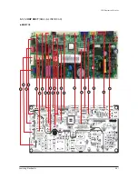
PCB Diagram and Parts List
Samsung Electronics
5-45
Wind-free 1way cassette type
(cont.)
- Main PBA (AM018/024NN1DCH/AZ)
1
2
3
4
6
5
7
8
9
10
11
12
13
14
15
16
17
18
19
20
21
22
23
24
Page 1: ...AM036 048JNCDCH AA AM006 009 012 018 024JNFDCH AA AM006 009 012 018 024JNGDCH AA AM072 096JNESCH AA AM054KNMDCH AZ AM007 009 012 018 020 024KNQDCH AZ AM007 009 012 018 020 024KNTDCH AZ AM005 007 009 0...
Page 2: ...eopeningmalfunction 2ndstage 4 53 4 4 10 BreakdownofEEV 2nd 4 54 4 4 11 ProblemwithEEVclosure 2nd 4 55 4 4 12 DetectionofFloatingSwitchofIndoorUnit sDrainPump 4 56 4 4 13 TheoperationalerrorofIndoorUn...
Page 3: ...4 56SumpSensorErrorDuetoProtectionControl 4 99 4 4 57 Comp DownduetoCompressorDischargeTemperaturesensor 4 100 4 4 58 3 phaseInputWiringerror 4 101 4 4 59 Comp DownbyCompressionRatioControl 4 102 4 4...
Page 4: ...ini 4way cassteettype 6 1 6 1 2 Slim1waycassettetype 6 2 6 1 3 BIGDuct 6 3 6 1 4 Ceiling 6 4 6 1 5 BigCeiling AM036 048JNCDCH AA 6 5 6 1 6 RAC NeoForte 6 6 6 1 7 WallMountedtype A3050 MAX 6 7 6 1 8 DU...
Page 5: ...tatic electricity Please wear insulation gloves before performing PCB repair and measurement Check if the place of installation is at least 2m away from electronic appliances such as TV video players...
Page 6: ...a danger to workers Please remove the oxide produced inside the pipe during the welding with nitrogen gas Using another gas may cause harm to the product or others 1 6 Precautions for Additional Suppl...
Page 7: ...fety devices Fuse Fuse Fuse Piping Connections Liquid Pipe Flare mm 6 35 6 35 6 35 inch 1 4 1 4 1 4 Gas Pipe Flare mm 12 7 12 7 12 7 inch 1 2 1 2 1 2 Drain Pipe Quick lock mm VP 20 OD 26 ID 20 VP20 OD...
Page 8: ...WE10N MWR WE10N External contact interface module MIM B14 MIM B14 MIM B14 Duct Receiver kits Receiver Receiver wire EEV kits 1 Mode HP Heat Pump HR Heat Recovery 2 Nominal cooling capacities are base...
Page 9: ...Micom Thermistors Safety devices Fuse Fuse Fuse Fuse Piping Connections Liquid Pipe Flare mm 6 35 6 35 6 35 6 35 inch 1 4 1 4 1 4 1 4 Gas Pipe Flare mm 12 7 12 7 12 7 12 7 inch 1 2 1 2 1 2 1 2 Drain...
Page 10: ...emote controller MWR WE10N MWR WE10N MWR WE10N MWR WE10N External contact interface module MIM B14 MIM B14 MIM B14 MIM B14 Duct Receiver kits Receiver Receiver wire EEV kits 1 Mode HP Heat Pump HR Hea...
Page 11: ...ipe Flare mm 6 35 6 35 6 35 9 52 inch 1 4 1 4 1 4 3 8 Gas Pipe Flare mm 12 7 12 7 12 7 15 88 inch 1 2 1 2 1 2 5 8 Drain Pipe Quick lock mm VP25 OD32 ID25 VP25 OD32 ID25 VP25 OD32 ID25 VP25 OD32 ID25 D...
Page 12: ...U wired remote controller MWR WE10N MWR WE10N MWR WE10N MWR WE10N External contact interface module MIM B14 MIM B14 MIM B14 MIM B14 Duct Receiver kits Receiver Receiver wire EEV kits 1 Mode HP Heat Pu...
Page 13: ...Fuse Fuse Fuse Piping Connections Liquid Pipe Flare mm 9 52 9 52 9 52 inch 3 8 3 8 3 8 Gas Pipe Flare mm 15 88 15 88 15 88 inch 5 8 5 8 5 8 Drain Pipe Quick lock mm VP25 OD32 ID25 VP25 OD32 ID25 VP25...
Page 14: ...ller MWR WE10N MWR WE10N MWR WE10N External contact interface module MIM B14 MIM B14 MIM B14 Duct Receiver kits Receiver Receiver wire EEV kits 1 Mode HP Heat Pump HR Heat Recovery 2 Nominal cooling c...
Page 15: ...id Low Refrigerant Type R 410A R 410A R 410A Control Method EEV INCLUDED EEV INCLUDED EEV INCLUDED Temperature Control Micom Thermistors Micom Thermistors Micom Thermistors Safety devices Fuse Fuse Fu...
Page 16: ...ontroller MWR WE10N MWR WE10N MWR WE10N External contact interface module MIM B14 MIM B14 MIM B14 Duct Receiver kits MRK A10N MRK A10N MRK A10N EEV kits 1 Mode HP Heat Pump HR Heat Recovery 2 Nominal...
Page 17: ...Sound Power High Mid Low Refrigerant Type R 410A R 410A Control Method EEV INCLUDED EEV INCLUDED Temperature Control Micom Thermistors Micom Thermistors Safety devices Fuse Fuse Piping Connections Li...
Page 18: ...WR WE10N External contact interface module MIM B14 MIM B14 Duct Receiver kits MRK A10N MRK A10N EEV kits 1 Mode HP Heat Pump HR Heat Recovery 2 Nominal cooling capacities are based on Indoor temperatu...
Page 19: ...Mid Low Refrigerant Type R 410A R 410A R 410A Control Method EEV INCLUDED EEV INCLUDED EEV INCLUDED Temperature Control Micom Thermistors Micom Thermistors Micom Thermistors Safety devices Fuse Fuse...
Page 20: ...ontroller MWR WE10N MWR WE10N MWR WE10N External contact interface module MIM B14 MIM B14 MIM B14 Duct Receiver kits MRK A10N MRK A10N MRK A10N EEV kits 1 Mode HP Heat Pump HR Heat Recovery 2 Nominal...
Page 21: ...0 35 0 31 0 Sound Power High Mid Low Refrigerant Type R 410A R 410A Control Method EEV INCLUDED EEV INCLUDED Temperature Control Micom Thermistors Micom Thermistors Safety devices Fuse Fuse Piping Co...
Page 22: ...10N MWR WE10N External contact interface module MIM B14 MIM B14 Duct Receiver kits MRK A10N MRK A10N EEV kits 1 Mode HP Heat Pump HR Heat Recovery 2 Nominal cooling capacities are based on Indoor temp...
Page 23: ...High Mid Low Refrigerant Type R 410A R 410A R 410A R 410A Control Method EEV INCLUDED EEV INCLUDED EEV INCLUDED EEV INCLUDED Temperature Control Micom Thermistors Micom Thermistors Micom Thermistors M...
Page 24: ...MR DH00U wired remote controller MWR WE10N MWR WE10N MWR WE10N MWR WE10N External contact interface module MIM B14 MIM B14 MIM B14 MIM B14 Duct Receiver kits MRK A10N MRK A10N MRK A10N MRK A10N EEV k...
Page 25: ...Method EEV NOT INCLUDED EEV NOT INCLUDED EEV NOT INCLUDED Temperature Control Micom Thermistors Micom Thermistors Micom Thermistors Safety devices Fuse Fuse Fuse Piping Connections Liquid Pipe FMR DH...
Page 26: ...l contact interface module MIM B14 MIM B14 MIM B14 Duct Receiver kits Receiver Receiver wire EEV kits MXD MEV series MXD MEV series MXD MEV series 1 Mode HP Heat Pump HR Heat Recovery 2 Nominal coolin...
Page 27: ...ontrol Method EEV NOT INCLUDED EEV NOT INCLUDED EEV NOT INCLUDED Temperature Control Micom Thermistors Micom Thermistors Micom Thermistors Safety devices Fuse Fuse Fuse Piping Connections Liquid Pipe...
Page 28: ...tact interface module MIM B14 MIM B14 MIM B14 Duct Receiver kits Receiver Receiver wire EEV kits MXD MEV series MXD MEV series MXD MEV series 1 Mode HP Heat Pump HR Heat Recovery 2 Nominal cooling cap...
Page 29: ...ontrol Method EEV INCLUDED EEV INCLUDED EEV INCLUDED Temperature Control Micom Thermistors Micom Thermistors Micom Thermistors Safety devices Fuse Fuse Fuse Piping Connections Liquid Pipe FMR DH00U mm...
Page 30: ...MWR WE10N MWR WE10N External contact interface module MIM B14 MIM B14 MIM B14 Duct Receiver kits Receiver Receiver wire EEV kits 1 Mode HP Heat Pump HR Heat Recovery 2 Nominal cooling capacities are b...
Page 31: ...ontrol Method EEV INCLUDED EEV INCLUDED EEV INCLUDED Temperature Control Micom Thermistors Micom Thermistors Micom Thermistors Safety devices Fuse Fuse Fuse Piping Connections Liquid Pipe Flare mm 6 3...
Page 32: ...MWR WE10N External contact interface module MIM B14 MIM B14 MIM B14 Duct Receiver kits Receiver Receiver wire EEV kits 1 Mode HP Heat Pump HR Heat Recovery 2 Nominal cooling capacities are based on I...
Page 33: ...7 12 7 12 7 12 7 15 88 15 88 inch 1 2 1 2 1 2 1 2 1 2 1 2 5 8 5 8 Drain Pipe Quick lock mm ID 18 HOSE ID 18 HOSE ID 18 HOSE ID 18 HOSE ID 18 HOSE ID 18 HOSE ID 18 HOSE ID 18 HOSE Dimensions Net Weigh...
Page 34: ...m ID 18 hose ID 18 hose ID 18 hose ID 18 hose ID 18 hose ID 18 hose Dimensions Net Weight kg 8 5 9 0 9 0 12 5 12 5 12 5 lbs 18 7 19 8 19 8 27 6 27 6 27 6 Shipping Weight kg 9 8 10 3 10 3 14 2 14 2 14...
Page 35: ...12 90 11 20 14 40 12 90 11 20 15 70 14 10 12 90 External Pressure Min Std Max Pa WG Sound Level Sound Pressure dBA 36 35 41 44 44 45 Refrigerant Type R410a R410a R410a R410a R410a R410a Control Metho...
Page 36: ...ssure High Mid Low dBA 40 0 37 0 44 0 40 0 Sound Power High Mid Low Refrigerant Type R 410A R 410A Control Method EEV INCLUDED EEV INCLUDED Temperature Control Micom Thermistors Micom Thermistors Safe...
Page 37: ...R WE10N External contact interface module MIM B14 MIM B14 Duct Receiver kits MRK A10N MRK A10N EEV kits M 1 Mode HP Heat Pump HR Heat Recovery 2 Nominal cooling capacities are based on Indoor temperat...
Page 38: ...8 0 46 0 43 0 Sound Power High Mid Low Refrigerant Type R 410A R 410A Control Method EEV INCLUDED EEV INCLUDED Temperature Control Micom Thermistors Micom Thermistors Safety devices Fuse Fuse Piping C...
Page 39: ...ernal contact interface module MIM B14 MIM B14 Duct Receiver kits MRK A10N MRK A10N EEV kits 1 Mode HP Heat Pump HR Heat Recovery 2 Nominal cooling capacities are based on Indoor temperature 27 C DB 1...
Page 40: ...Type R 410A R 410A Control Method EEV NOT INCLUDED EEV NOT INCLUDED Temperature Control Micom Thermistors Micom Thermistors Safety devices Fuse Fuse Piping Connections Liquid Pipe Flare mm 6 35 9 52 i...
Page 41: ...odule MIM B14 MIM B14 Duct Receiver kits Receiver Receiver wire EEV kits MXD MEV series MXD MEV series 1 Mode HP Heat Pump HR Heat Recovery 2 Nominal cooling capacities are based on Indoor temperature...
Page 42: ...8 Drain mm VP25 OD25 ID 20 VP25 OD25 ID 20 inch Weight NetWeight kg 33 5 42 5 ShippingWeight kg 39 5 48 5 Dimensions Net Dimensions W H D mm 1350 235 675 1650 235 675 inch Shipping Dimensions W H D mm...
Page 43: ...ight kg ShippingWeight kg Net Dimensions W H D mm Shipping Dimensions W H D mm Functions Auto restart O O Auto swing O O Group individual control O O External contact control O O Trouble shooting by L...
Page 44: ...nsions NetWeight kg 35 0 35 0 35 0 35 0 36 5 ShippingWeight kg 39 0 39 0 39 0 39 0 40 5 Net Dimensions W H D mm 1150 320 480 1150 320 480 1150 320 480 1150 320 480 1150 320 480 Shipping Dimensions W H...
Page 45: ...2 ID 25 Dimensions NetWeight kg 54 0 54 0 54 0 56 0 56 0 ShippingWeight kg 68 0 68 0 68 0 70 0 70 0 Net Dimensions W H D mm 1200 360 650 1200 360 650 1200 360 650 1200 360 650 1200 360 650 Shipping Di...
Page 46: ...600x220 1225x600x220 1225x600x220 lbs 37 2 23 62 8 66 37 2 23 62 8 66 37 2 23 62 8 66 48 23 23 62 8 66 48 23 23 62 8 66 Shipping Dimensions mm 1035x690x310 1035x690x310 1035x690x310 1335x690x310 1335x...
Page 47: ...945x600x220 1225x600x220 1225x600x220 lbs 37 2 23 62 8 66 37 2 23 62 8 66 37 2 23 62 8 66 48 23 23 62 8 66 48 23 23 62 8 66 Shipping Dimensions mm 1035x690x310 1035x690x310 1035x690x310 1335x690x310 1...
Page 48: ...65x460x910 1465x460x910 inch Shipping Dimensions W H D mm 1612 x 519 x 984 1612 x 519 x 984 inch BypassTube SOLENOIDVALVE Assy FDF6A48 Assy FDF6A48 CheckVALVE ID9 6 ID12 9 ID9 6 ID12 9 Panel Size Mode...
Page 49: ...5 OD 32 ID 25 Dimensions NetWeight kg 31 2 31 2 31 2 31 2 31 2 ShippingWeight kg 35 0 35 0 35 0 35 0 35 0 NetDimensions W H D mm 850 x 250 x 700 850 x 250 x 700 850 x 250 x 700 850 x 250 x 700 850 x 2...
Page 50: ...kg 45 2 45 2 45 2 ShippingWeight kg 50 0 50 0 50 0 NetDimensions W H D mm 1 200 x 250 x 700 1 200 x 250 x 700 1 200 x 250 x 700 ShippingDimensions W H D mm 1 429 x 320 x 779 1 429 x 320 x 779 1 429 x...
Page 51: ...imensions W H D mm 850 x 250 x 700 850 x 250 x 700 ShippingDimensions W H D mm 1 064 x 320 x 784 1 064 x 320 x 784 Funtion Autorestart o o Autoswing x x Group Individualcontrol o o Exteralcontactcontr...
Page 52: ...rmistors Safetydevices Fuse Fuse Fuse Piping Connections LiquidPipe Flare mm 6 35 6 35 6 35 inch 1 4 1 4 1 4 GasPipe Flare mm 12 70 12 70 12 70 inch 1 2 1 2 1 2 DrainPipe Quicklock mm VP20 OD 25 ID 20...
Page 53: ...allation conditions 5 Specifications may be subject to change without prior notice for product improvement Model JSF 1 AM007NN1DCH AM009NN1DCH AM012NN1DCH Standard accessories Installationmanual O O O...
Page 54: ...Micom Thermistors Safety devices Fuse Piping Connections Liquid Pipe Flare mm 6 35 9 52 inch 1 4 3 8 Gas Pipe Flare mm 12 7 15 88 inch 1 2 5 8 Drain Pipe Quick lock mm VP20 OD 25 ID 20 VP20 OD 25 ID 2...
Page 55: ...Duct Receiver kits Receiver Receiver wire EEV kits Indoor Unit cont Q Wind free 1way cassette type 1 Mode HP Heat Pump HR Heat Recovery 2 Nominal cooling capacities are based on Indoor temperature 27...
Page 56: ...2 420 326 Functions Auto Restart O Auto Swing O Group Individual Control O External Contact Control O Trouble Shooting by LED O Standard Accessories Installation Manual O Operation Manual O Pattern Sh...
Page 57: ...Weight kg 25 0 25 0 25 0 25 0 29 0 29 0 29 0 lbs 55 1 55 1 55 1 55 1 63 9 63 9 63 9 Net Dimensions W H D mm 947 x 281 x 947 947 x 281 x 947 947 x 281 x 947 947 x 281 x 947 947 x 365 x 947 947 x 365 x...
Page 58: ...MIM B14 MIM B14 MIM B14 MIM B14 MIM B14 MIM B14 MIM B14 1 Mode HP Heat Pump HR Heat Recovery 2 Nominal cooling capacities are based on Indoor temperature 27 C DB 19 C WB Outdoor temperature 35 C DB 24...
Page 59: ...needed Wall mounted Ceiling No receiver needed MR DH00 Cassette Duct Receiver needed MR EH00 Cassette Duct Receiver needed MR KH00 360 cassette AR EH03E All model Wired remote controller Multi functio...
Page 60: ...154MBH EEVkit MXD E24K132A 2indoorunits 7 15 5 17 31K HP Wall mounted Ceiling Option MXD E24K200A 2indoorunits 7 15 5K MXD E32K200A 2indoorunits 7 31K MXD E24K232A 3indoorunits 7 15 5 17 31K HP Wall...
Page 61: ...Samsung Electronics 3 1 Q Necessary Tools 3 Disassembly and Reassembly Item Remark Screw Driver Monkey Spanner Screw Driver Nipper Electric Motion Driver L Wrench...
Page 62: ...ll and open it 2 Separate 1 clip from the Panel and tilt the Grill to 45 and separate the Grille from the Panel 3 Separate the Filter from the Panel 4 Separate 3 cover screws from it 5 Unscrew 6 fixed...
Page 63: ...Disassembly and Reassembly Samsung Electronics 3 3 No Parts Procedure Remark 6 Press the left and right Hooks to separate the Panel from the Indoor Unit...
Page 64: ...ILLE as shown in the figure 4point 2 Remove the FILTER from the PANEL 3 Remove the 3 COVER SCREW as shown in the figure 4 Remove the 7 screws fixed in PANEL and then remove the PANEL Use Screw Driver...
Page 65: ...PANEL And FILTER Continues 6 Open the GRILLE and then separate the CLIP WIRE 7 Remove the screws fixed in COVER DISPLAY COVER MOTOR RIGHT and then remove the COVER DISPLAY COVER MOTOR RIGHT Use Screw...
Page 66: ...R Continues 9 Remove the 4 screws fixed in STEP MOTOR and then remove the MOTOR Use Screw Driver 10 Remove the 4 HINGE and then separate the BLADE H 11 Separate the SENSOR HUMIDITY 12 Remove the 5 scr...
Page 67: ...ng screws from the Drain Pan Use Screw Driver 2 Pull the Drain Pan to separate them from the Indoor Unit When disassembling the Pan be careful not to touch the heat exchanger board with a bare hand 3...
Page 68: ...ssembly 3 8 Samsung Electronics No Parts Procedure Remark 2 Separate 8 connecters on the PCB of the Indoor Unit 3 Separate the Control In from the Indoor Unit 4 Drain Sub 1 Push the hook on the Drain...
Page 69: ...er 1 Undo fixing screw in the Heat Exchanger Use Screw Driver 2 Separate an Indoor Sensor from the Heat Exchanger 3 Separate the Heat Exchanger from the Indoor Unit 6 Cross Fan 1 Undo 3 fixing screws...
Page 70: ...nics No Parts Procedure Remark 3 Separate the Cross Fan from the Indoor Unit 7 Drain Pump 1 Separate fixing screw in the Cover Drain Pump Use Screw Driver 2 Separate the Drain Hose from the Drain Pump...
Page 71: ...k 1 MOTOR BLOWER 1 Detach the motor connectors from the PCB 2 Unscew 16 screws and detach Cabinet Base Blower Use Screw Driver 3 Unscrew 8 screws and detach Case Blower Use Screw Driver 4 Unscrew 4 bo...
Page 72: ...lt and Separate Blower from the motor Use Screw Driver 2 EVAPORATOR DRAIN PAN 1 Detach EEV and Sensor connectors from the PCB Use Screw Driver 2 Unscrew 8 screws and Detach Cover Pipe Use Screw Driver...
Page 73: ...Disassembly and Reassembly Samsung Electronics 3 13 No Parts Procedure Remark 4 Unscrew 10 screws and detach Drain Pan from the indoor unit Use Screw Driver 5 Separate Evaporator from the indoor unit...
Page 74: ...owards the product s interior to open the Grille 2 Push up the green knob in the Open direction and detach the white link from the panel Detach the safety clip 3 Remove the 2 fixed screws to remove th...
Page 75: ...Hangers at both sides of the panel inwards and rotate them 90 degrees to remove it from the indoor unit s Hock Remove the panel from the indoor unit 2 Control Box 1 Disconnect the Connector Wire that...
Page 76: ...Unscrew the screw fixed on the Bell Mouth Use Screw Driver 2 Push the Bell Mouth in the direction opposite to where it s installed on the Control Box to remove it 4 Drain Pan 1 Unscrew the screws on t...
Page 77: ...e drainage hose from the Drain Pump Use Screw Driver 2 Remove the 2 screws and take the Drain Hose out from the indoor unit to disassemble the transparent Drain Hose fixed on the side of the indoor un...
Page 78: ...e three hexangular nuts on the Motor counterclockwise to remove the nuts Take the Motor Wires attached to these three locations out with your hands prior to removing the Motor 8 Evaporator 1 Remove th...
Page 79: ...y Samsung Electronics 3 19 No Parts Procedure Remark 3 Remove the screw of the Cover Pipe that is used to fix the In Out Pipe Remove the In Out Pipe Use Screw Driver 4 Remove the Heat Exchanger from t...
Page 80: ...r 1 Disassemble the Cabinet Top Motor Unscrew 8 screws 2 Disassemble 2 Cover Blower Uppers After unscrewing 2 screws Disassemble the Cover Blower Upper with pushing its hook 3 Disassemble the Cover Co...
Page 81: ...Motor earth wire connected to the Partition Unscrew a screw 6 Disassemble the band Motor for fixing the Motor Unscrew 2 screws 7 After disassembling the Motor and Blower for the set disassemble the Bl...
Page 82: ...rews 3 Disassemble the Drain Cushion from the set 3 Ass y Evap The Evaporator should be disassembled after disassembling the Cover Control 1 3 and the Drain Pan 2 1 2 2 2 3 1 Disassemble the Cover Pip...
Page 83: ...rt Evap RH Unscrew 2 screws 5 Disassemble the Evaporator form the set 4 Ass y Control In The Control In should be disassembled after disassembling the Cover Control 1 3 1 Disassemble all Control Wires...
Page 84: ...e Control dis assemble the Case Control from the set after unscrewing the screw connected to the direc tion of Blower Disassemble if after disassembling the Cabinet Top Motor 1 1 5 In case of disassem...
Page 85: ...embly Samsung Electronics 3 25 Q Duct type Slim3 No Parts Procedure Remark 1 Filter 1 DPull out the Filter as picture 1 or picture 2 2 DIf it is necessary after disassembling 8 indi cating screws deta...
Page 86: ...the side of the set the procedure of disassembling the Filter is just as the above 5 Bracket Outlet 1 After disassembling 13 indicating screws detach Ass y Cabinet Top Motor 2 After disassembling 3 i...
Page 87: ...3 After disassembling 2 indicating screws detach the Cover Control 4 Detach the Motor Wire Connected to PCB and Capacitor 5 After disassembling the indicating screws detach the wire connected to the P...
Page 88: ...disassembling the Motor and Blowers detach the Blowers from the axis of the Motor by 3mm inner hexagon spanner 3 Drain Pan 1 After disassembling 15 indicating screws detach Ass y Cabinet Top Evap 2 Af...
Page 89: ...procedures above detach the Evaporator 1 After disassembling 2 indicating screws detach Ass y Cover Pipe 2 Detach the Sensor from the Control Box including 2 Sensors 3 After disassembling 2 indicatin...
Page 90: ...r disas sembling the Cover Control 1 Detach all the wires connected to the PCB 2 If only the disassembly of PCB required press the Pothook and detach the PCB from the set 3 If only the disassembly of...
Page 91: ...No Parts Procedure Remark 7 Ass y Cross Fan 5 Detach the Transformer after disassembling 2 indicating screws Work is possible after disassembling the Case PCB 6 Ass y Bracket Outlet 2 After disassembl...
Page 92: ...ilter 1 After disassembling 16 places indicating screws detach Ass y Cabi Bottom Blower Use Screw Driver 2 Detach from Ass y Control In the capacitor connection wire between the Motor Fan and housing...
Page 93: ...Procedure Remark 4 After disassembling 2 places indicating screws detach Fan Motor and Blower from the set 2 Control In 1 After disassembling 1 Indicating screw detach the Cover control Use Screw Dri...
Page 94: ...ocedure Remark 3 Disassemble 4 indicating screws and detach Control In from the set Use Screw Driver 3 Drain Pan Work is possible when Disassembling the Ass y Cabi Bottom Blower 1 Disassemble 7 indica...
Page 95: ...ng Electronics 3 35 No Parts Procedure Remark 2 Disassemble 2 indicating screws and detach Holder Pipe Use Screw Driver 3 Disassemble 4 indicating screws and detach the Drain Pan 2 screws each at left...
Page 96: ...n Disassembling the Ass y Drain Pan 1 Disassemble 5 indicating screws to detach Cover Pipe Use Screw Driver 2 Disassemble Sensor on the Evap 3 Disassemble 4 indicating screws which are in the near of...
Page 97: ...Blower Motor 1 After disassembling 15 places indicating screws detach Ass y Cabi Bottom Blower Use Screw Driver 2 Detach from Ass y Control In the capacitor connection wire between the Motor Fan and...
Page 98: ...re Remark 4 After disassembling 2 places indicating screws detach Fan Motor and Blower from the set Use Screw Driver 3 Drain Pan 1 After disassembling 1 Indicating screw detach the Cover control Use S...
Page 99: ...ocedure Remark 3 Disassemble 4 indicating screws and detach Control In from the set Use Screw Driver 3 Drain Pan Work is possible when Disassembling the Ass y Cabi Bottom Blower 1 Disassemble 6 indica...
Page 100: ...and detach Holder Pipe Use Screw Driver 3 Disassemble 6 indicating screws and detach the Drain Pan Use Screw Driver 3 screws each at left and right side 4 Evap Work is possible when Disassembling the...
Page 101: ...amsung Electronics 3 41 No Parts Procedure Remark 2 Disassemble Sensor on the Evap 3 Disassemble 2 indicating screws which are in the near of Hanger Plate to detach the Evap 1 screw each at left and r...
Page 102: ...009 012 015 018JNMDCH AA No Parts Procedure Remark 1 Assy fan parts 1 Disassemble the Cabinet blower Unscrew 19 screws 2 Disassemble the Partition front from Partition Unscrew 8 screws 3 Rotate the as...
Page 103: ...Disassembly and Reassembly Samsung Electronics 3 43 No Parts Procedure Remark 2 DrainPan 1 Disassemble the cabinet drain Unscrew 7 screws 2 Disassemble the Drain pan Unscrew 4 screws...
Page 104: ...44 Samsung Electronics No Parts Procedure Remark 3 Drainpump 1 Disassemble the drain pump kit from the set Unscrew 2 screws 2 Disassemble the drian pump case Unscrew 4 screws 3 Disassemblethedrianpum...
Page 105: ...Disassembly and Reassembly Samsung Electronics 3 45 No Parts Procedure Remark 4 Evaporator 1 Disassemble the Cover pipe Unscrew 5 screws 2 Disassemble the Evaporator Unscrew 4 screws...
Page 106: ...Disassembly and Reassembly 3 46 Samsung Electronics No Parts Procedure Remark 5 MainPBA 1 Disassemble the Case Control Unscrew 3 screws 2 Disassemble the Evaporator Unscrew 4 screws...
Page 107: ...AM024 027 030 036 048JNHDCH AA Drain Pump Built in AM054KNMDCH AZ Drain Pump Option No Parts Procedure Remark 1 Drain Pan 1 Disassemble the cabinet blower Unscrew 17 screws 2 Disassemble the cabinet...
Page 108: ...ung Electronics No Parts Procedure Remark 2 Assyfanparts 1 Disassemle the case blower from partition Unscrew 10 bolts by using wrench and driver 2 RatatetheAssyfanpartsinCCWdirection 3 PullouttheAssyf...
Page 109: ...ng Electronics 3 49 No Parts Procedure Remark 3 Drain pump 1 Disassemble the drain pump kit from the set Unscrew 2 screws 2 Disassemble the drian pump case Unscrew 4 screws 3 Disassemble the drian pum...
Page 110: ...0 Samsung Electronics No Parts Procedure Remark 4 Evaporator 1 Disassemble the Evaporator Unscrew 4 screws 5 Main PBA 1 Disassemble the Case Control Unscrew 3 screws 2 Detach all connect cable 3 Disas...
Page 111: ...pen the Grille by sliding 4 position and removing 4 screws 2 Detach the Air Inlet Grille 3 Detach the Cover side by removing 1 screw and sliding Cover 4 Open the cover of Component Electrical Box by r...
Page 112: ...No Parts Procedure Remark 2 Fan Motor 1 Disconnect 2 wires of Motor 2 Detach Holder Motor by removing 2 screws 3 Detach the Upper case of Fan AM112JNCDKH 3EA AM140JNCDKH 4EA 4 Detach Bracket Grille b...
Page 113: ...53 No Parts Procedure Remark 3 DrainPan 1 Detach the Cabinet Front by remov ing 7 screws 2 Remove 1 screw in the middle of drain pan 3 Detach the Drian pan Be careful that there might be some water le...
Page 114: ...ics No Parts Procedure Remark 4 Evaporator 1 First Separate the connector of the expansion valve 2 Detache the Cover Pipe by removing 2 screws 3 Detache the Cover Evap LF RH by removing 4 screws 4 Det...
Page 115: ...and Reassembly Samsung Electronics 3 55 No Parts Procedure Remark 5 SteppingMotor 1 Detach the Connector 2 DetachetheSteppingMotorby emoving2screws 6 HolderBlade 1 Remove 4 screws at both side of the...
Page 116: ...ectronics Q CEILING No Parts Procedure Remark 1 Electrical Part 1 Open the Grille by pressing 3 position center and both side 2 Detach the Air Inlet Grille 3 Open the Cover of Component Electrical Box...
Page 117: ...assembly and Reassembly Samsung Electronics 3 57 No Parts Procedure Remark 2 Fan Motor 1 Detach the screw and untie earth wire of Motor 2 Disconnect of housing of Motor Wire 3 DisconnecttheCapacitorWi...
Page 118: ...sembly 3 58 Samsung Electronics No Parts Procedure Remark 4 Loosen the Guard Safety by removing 6 screws 5 Detach the Upper Case of Fan 2EA 6 Loosen the 4 screws what is fix the Motor 7 Detach the Fan...
Page 119: ...emark 8 Loosen the set fixing bolts with a M3 wrench 9 Detach the Fan 3 DrainPan 1 Disconnect the Display PCB Wire as shown in picture white housing 2 Disconnect the Step Motor Wire as shown in pictur...
Page 120: ...cs No Parts Procedure Remark 4 Loosen the 3 screws of Front Side 5 Disassemble the assembly Front Cover Part 6 Disconnect the Step Motor Wire as shown in picture 7 Detach the Wire Clamp fixed in Base...
Page 121: ...ng Electronics 3 61 No Parts Procedure Remark 9 Loosen the screw what is fix with Base Part and Drain Pan Upper Side 2EA 10 Loosen the screw what is fix with Base Part and Drain Pan Lower Side 2EA 11...
Page 122: ...the Thermistor Wire as shown in picture white housing 2 Loosen the 2 screws shown in picture 3 Loosen the 2 screws shown in picture and remove Plastic Part white 4 Loosen the 2 screws shown in pictur...
Page 123: ...Disassembly and Reassembly Samsung Electronics 3 63 No Parts Procedure Remark 6 Loosen the 2 screws as shown in picture 7 Detach the Plastic Cover as shown in picture 8 Detach the Evaporator assembly...
Page 124: ...er assembly as shown in picture 2 Loosen the 2 screws as shown in picture 3 Disassemble the Blade and Stepping Motor assembly and remove the 2 Screws Stepping Motor 6 DisplayPCB 1 Loosen the 3 screws...
Page 125: ...e Front Grille by pulling right and left sides of the hook 3 Loosen 1 of the right screw CCW and detach the Terminal Cover Use Screw Driver 4 Detach the thermistor from the Front Grille 5 Loosen 2 fix...
Page 126: ...ol In MainPCB 1 Take all the connector of PCB upper side out Inclusion Power Cord 2 Detach the outdoor unit connection wire from the Terminal Block 3 Loosen 4 fixing screws CCW of Ass y Control In Use...
Page 127: ...ide 4 Loosen the 4 fixing screws CCW of right and left side Use Screw Driver 5 Lifting the Heat Exchanger up a little to push the up side for separation from the indoor unit First checkComp Downandthe...
Page 128: ...1 PANEL FRONT 1 Stop the driving of air conditioner and shut off main power supply 2 Detach FILTER PRE from the PANEL FRONT 3 Cover Panel is assembled on bottom of indoor unit as shown in the figure...
Page 129: ...by Hook in center area and side area 5 Separate the hook after pushing both end of Cover Panel as shown in the figure Watch out for the damage of the hook 6 Raise front part upward obliquely as shown...
Page 130: ...No Parts Procedure Remark Assembly of Cover Panel after service end Reassembly is in the reverse order of the removal Piping and drain hose must be careful not to damage and Progress must be done wit...
Page 131: ...T from the main frame unfasten 2 screws at the bottom use Screw Driver 8 To detach the COVER PANEL from the main frame loosen 4 HOOK Structures When separate the hook Use the screw Driver Screw Driver...
Page 132: ...Disassembly and Reassembly 3 72 Samsung Electronics No Parts Procedure Remark 9 Remove the Panel Frame from the Main Frame as shown on the right side...
Page 133: ...BAWire When you separate the connector pull pressing the locking button 2 Lossen Stepping Motor EEV Display Sensor SPI FuseWire When you separate the connector pull pressing the locking button 3 Losse...
Page 134: ...Remark 5 EVAPORATOR 9 Take off the CASE CONTROL from the main frame after loosen the remaining connector When you separate the connector pull pressing the locking button 3 TRAY DRAIN 1 To detachTRAY...
Page 135: ...ts Procedure Remark 4 Evaporator 1 Detach the HOLDER PIPE 2 Unfasten the screw at the left side use Screw Driver 3 Unfasten the screw at the right side use Screw Driver 4 To detach Evaporator from the...
Page 136: ...y 3 76 Samsung Electronics No Parts Procedure Remark 5 FAN MOTOR CROSS FAN 1 Unfasten the screw use Screw Driver 2 Detach the FAN Motor case 3 Unfasten the screw a little use Screw Driver 4 Pull the C...
Page 137: ...Front Grille 1 Stop the air conditioner operation and shut off the main power 2 Open the FRONT GRILLE and pull out from the PANEL FRONT 3 Detach COVER TERMINAL from the PANEL FRONT Use Screw Driver 4...
Page 138: ...en the screw 2 Detach COVER CONTROL from the CASE CONTROL 3 Loosen stepping motor wire and detach the hook of main frame 4 To detach TRAY DRAIN from the main frame pull the bottom of the TRAY DRAIN to...
Page 139: ...t the Connector Wire that is connected to the indoor unit s PBA from the PBA 4 Unfasten the 2 screw use Screw Driver 5 Take off the CASE CONTROL from the main frame 3 EVAPORATOR 1 Unfasten the screw a...
Page 140: ...Remark 3 Detach the HOLDER PIPE 4 Take off the EVAPORATOR from the main frame 5 FAN MOTOR CROSS FAN 1 Unfasten the screw use Screw Driver 2 Take off the from the main frame 3 Unfasten the screw a litt...
Page 141: ...own ward Two safety clips are mounted to the front grille to prevent it from dropping 2 Detach the safity clip and take up the grille 3 Remove the 2 fixed screws to remove the Control Box Cover Use Sc...
Page 142: ...ners 7 Press the Hangers at both sides of the panel inwards to remove it from the indoor unit s hook Remove the panel from the indoor unit 2 Control Box 1 Disconnect the Connector Wire that is con nec...
Page 143: ...Unscrew the screw fixed on the Bell Mouth Use Screw Driver 2 Push the Bell Mouth in the direction oppo site to where it s installed on the Control Box to remove it 4 DrainPan 1 Unscrew the screws on t...
Page 144: ...drainage hose from the Drain Pump Use Screw Driver 2 Remove the 2 screws and take the Drain Hose out from the indoor unit to disas semble the transparent Drain Hose fixed on the side of the indoor un...
Page 145: ...he three hexangular nuts on the Motor counterclockwise to remove the nuts Take the Motor Wires attached to these three locations out with your hands prior to removing the Motor 8 Evaporator 1 Remove t...
Page 146: ...y 3 86 Samsung Electronics No Parts Procedure Remark 3 Remove the screw of the Cover Pipe that is used to fix the In Out Pipe Remove the In Out Pipe Use Screw Driver 4 Remove the Heat Exchanger from t...
Page 147: ...ASS Y INLET PART 1 Open the ASS Y INLET and separate the safety clips If there is a dust collector in the ASS Y INLET separate the connector wire as well 3 ASS Y MAIN PCB PART 1 Remove the 1 screw wh...
Page 148: ...ISPLAY Use Screw Driver Please be careful you do not scratch the blade during unscrewing 2 Separate the CONNECTOR WIRE of ASS Y PANEL PCB 3 Remove the 2 screws from the ASS Y OUTLET SHUTTER and remove...
Page 149: ...xed to PARTITION Use Screw Driver 2 Remove the 2 screws which is fixed to COVER EVAP COLLECTOR and then sepa rate the ASS Y EVAP Use Screw Driver Be careful not to crush the FIN during ASS Y EVAP disa...
Page 150: ...WER Use Monkey Spanner 2 Remove the 3 fixing nut of the MOTOR and remove the ground wire fixing screw Use Monkey Spanner 7 ASS Y CONTROL IN PART 1 Remove the 2 screws which is fixed to COVER CONTROL U...
Page 151: ...t recovery operation 3 In the case of major repairs that power unconnected Collect all of the refrigerant to the refrigerant bombe Using the refrigerant recovery apparatus and refrigerant bombe 2 ASS...
Page 152: ...iver 2 Lift up the FRONT PANEL and separate it 3 Separate the wire from the holder wire and place the FRONT PANEL in the flat floor 4 Separate the wire from the holder wire of FRONT PANEL rear 5 Remov...
Page 153: ...Remark 5 OUTLET GRILLE PART 1 Remove the 2 screws from the BRACKET FRONT BLOWER of OUTLET GRILLE Use Screw Driver 2 Remove the 14 screws from the COVER TOP Use Screw Driver 3 Separate the COVER TOP 4...
Page 154: ...a fire extinguisher in preparation for an emergency 1 Remove the high pressure pipe flare nut Use Monkey Spanner 2 Carefully separate the low pressure pipe 9 8 inch using gas welding machine Take care...
Page 155: ...ART 1 Separate the connector of motor drive capacitor 2 Remove the 8 screws from the COVER FAN BLOWER DUCT Use Screw Driver 3 Separate the COVER FAN BLOWER 4 Remove the 2 screws from the FAN MOTOR BRA...
Page 156: ...3 96 Samsung Electronics No Parts Procedure Remark 6 Hold up with both hands a FAN and MOTOR and then pull out the FAN and MOTOR...
Page 157: ...CONCEALED No Parts Procedure Remark 1 Cabinnet 1 Unscrew fixed screw of the upper part cabinet and please separate 2 Please separate front cabinet All the procedure has to be verified because the cov...
Page 158: ...nscrew two fixed screws and please separate heat exchanger cover 2 Unscrew fixed screw on both side of heat exchanger plate And then pulls heat exchanger to the right side and please separate 3 DrainP...
Page 159: ...ss hopes for DRAIN PAN isolation work in this work earlier 2 Unscrew MOTOR BRACKET fixation screw located in the front surface and please separate 3 Unscrew MOTOR BRACKET fixation screw located in the...
Page 160: ...Fan 5 Please separate screw between the MOTOR and the MOTOR BLACKET 6 Please separate screw between the MOTOR BLACKET and the FAN BLOWER 7 Please separate screw between the MOTOR BLACKET and the FAN B...
Page 161: ...T MID by pulling down wards 3 Please unscrew the GRILLE screw and sepa rate the GRILLE 4 Please unscrew the FRONT MID Screw and separate the FRONT MID 5 Please unscrew the FRONT UPPER the FRONT SIDE s...
Page 162: ...s No Parts Procedure Remark 2 Heat Exchanger 1 Please unscrew the screw and separate the COVER 2 Please unscrew the SIDE CABINET screw 3 Please disassemble the fixing plate of heat exchanger and separ...
Page 163: ...Samsung Electronics 3 103 No Parts Procedure Remark 3 Control Box 1 Please unscrew the screw and separates the C BOX COVER 2 Please unscrew the screw and separates the C BOX...
Page 164: ...E screw and separates the MOTOR CABINET 2 Please separate screw between the MOTOR and the MOTOR BLACKET 3 Please separate screw between the MOTOR BLACKET and the FAN BLOWER 4 Please separate screw bet...
Page 165: ...Control Unscrew 2 screws You must turn off the Power before disassembly 2 Motor Fan Service from Top Bottom side 1 Disassemble the connection wire to take the Motor Fan out 2 Disassemble the Canibet T...
Page 166: ...cedure Remark 5 Disassemble C BOX side Case Blower Unscrew 1 Blower screw using 3mm wrench Unscrew 6 screws 6 Disassemble 1 Holder Motor Unscrew 2 screws 7 Disassemble Blower screw of opposite side Un...
Page 167: ...isassemble motor wire from 3 holder wires Please be careful Avoiding injury when disassembly the steel blower 9 Disassemble Case blower Unscrew 6 screws 10 Disassemble the Bell mouth for Blower change...
Page 168: ...3 108 Samsung Electronics No Parts Procedure Remark 3 Control Box 1 Disassemble Evap Sensor wire EEV wire Motor wire and Solenoid V V wire 2 Disassemble the Case Control Unscrew 6 screws...
Page 169: ...3 109 No Parts Procedure Remark 4 Evap Service from Top side 1 Disassemble The Case Evap Top Unscrew 6 screws 2 Disassemble the Link Screw Unscrew 3 screws 3 Disassemble the Case Evap Top 4 Disassemb...
Page 170: ...3 110 Samsung Electronics No Parts Procedure Remark 4 Evap 5 Disassemble The Cover pipe Unscrew 4 screws 6 Remove The cable tie on the Support Evap 7 Disassemble The Evap Unscrew 4 screws...
Page 171: ...msung Electronics 3 111 No Parts Procedure Remark 4 Evap 8 Disassemble the Case Fan Top Unscrew 6 screws 9 Disassemble Evap Sensor wire EEV wire and Solenoid V V wire from C BOX 10 Disassemble the Eva...
Page 172: ...Bottom side 1 Disassemble The Case Evap Bottom Unscrew 7 screws 2 Disassemble the Link Screw Unscrew 3 screws 3 Disassemble the Case Evap Bottom 4 Disassemble The Case Fan Bottom Unscrew 6 screws 5 Di...
Page 173: ...Samsung Electronics 3 113 No Parts Procedure Remark Evap 7 Disassemble Evap Sensor wire EEV wire and Solenoid V V wire from C BOX 8 Disassemble The Evap Unscrew 2 screws 3 2 1...
Page 174: ...NMDCH AA No Parts Procedure Remark 1 Motor Blower 1 Disassemble the Cabinet Bottom Fan Unscrew 10 screws 2 Disassemble the Case Filter Pre 3 Disassemble the Cabinet Bottom Evap Unscrew 10 screws 4 Dis...
Page 175: ...e Remark 6 Disconnect the wire between assy control out and motor 7 Disassemble the 2 Holder Motor Unscrew 2 screws 8 Disassemble the fan casing Unscrew 8 screws 9 Disassemble the motor Unscrew 2 scre...
Page 176: ...Bottom Evap Unscrew 7 screws 2 Pull the Drain Pan Out 3 Disassemble the drain Pump Unscrew 5 screws and disassemble 2 conectors 3 EVAP 1 Disassemble the Support Evap Unscrew 1 screws 2 Disassemble the...
Page 177: ...Samsung Electronics 3 117 No Parts Procedure Remark 4 Disassemble the Evap Unscrew 3 screws Then pull the Evap out 4 Control 1 Disassemble the Case Control Unscrew 2 screws...
Page 178: ...Parts Procedure Remark 5 PBA 1 Disassemble the main PBA Unscrew 1 screw disassembe conectors 2 Disassemble the case PBA Unscrew 2 screws 3 Disassemble the BLDC PBA Unscrew 1 screw 6 Frame 1 Disassembl...
Page 179: ...27 030 036 048MNMDCH AA No Parts Procedure Remark 1 Common 1 Disassemble the Cabinet Bottom Fan Unscrew 11 screws 2 Disassemble the Case Filter Pre 3 Disassemble the Cover Control Unscrew 2 screws 4 D...
Page 180: ...ics No Parts Procedure Remark 2 Drain Pan Evap 1 Disassemble the Drain Pan from the set 2 Disassemble the Cover Pipe Unscrew 2 screws 3 Disassemble the Support Evap Unscrew 1 screws 4 Disassemble the...
Page 181: ...Fan 1 Disassembl the connection wire the take the Motor Fan out 2 Disassemble the 3 holder motor Unscrew 2 screws 3 Disassemble the fan casing Unscrew 4 screws 4 Disassemble the holder shaft Unscrew...
Page 182: ...cs No Parts Procedure Remark 6 Disassemble the motor Unscrew 1 screw 7 Disassemble the fan Unscrew 5 screws 4 Cushion 1 Disassemble the Assy Cushion Right Unscrew 1 screws 2 Disassemble the Seal Cushi...
Page 183: ...e Case Control Unscrew 2screws 6 PBA 1 Disassemble the main PBA Unscrew 1 screw disassembe conectors 2 Disassemble the case PBA Unscrew 2 screws 3 Disassemble the BLDC PBA Unscrew 1 screw Global Duct...
Page 184: ...d shut off the main power 2 Open the FRONT GRILLE and pull out from the PANEL FRONT 3 Detach COVER TERMINAL from the PANEL FRONT Use Screw Driver 4 Loosen connector wire white and detach the temperatu...
Page 185: ...hook of main frame 2 To detach TRAY DRAIN from the main frame pull the bottom of the TRAY DRAIN towards you 3 To detach TRAY DRAIN from the main frame pull the bottom of the TRAY DRAIN towards you 3 C...
Page 186: ...Disassembly and Reassembly 3 126 Samsung Electronics No Parts Procedure Remark 4 Loosen MOTOR wires white 5 Take off the CASE CONTROL from the main frame use Screw Driver...
Page 187: ...e STEP UP DOWN connector CN802 When you separate the connector pull pressing the locking button 2 Loosen the EEV connector CN801 When you separate the connector pull pressing the locking button 3 Loos...
Page 188: ...ing button 5 Loosen the Humidity sensor connector CN401 Option connector The terminal is locking type So when you separate terminals pull pressing the button 6 Loosen the DISPLAY connector CN501 The t...
Page 189: ...ouch the components Please hold the PBA both side 9 Loosen the Motor connector CN701 When you separate the connector pull pressing the locking button 10 Take off the main PBA from the ASS Y Control in...
Page 190: ...ts Procedure Remark 2 Unfasten the screw at the left side use ScrewDriver 3 Detach the HOLDER PIPE use Screw Driver 4 Detach the BRACKET EVAP use Screw Driver 5 Detach the HOLDER EVAP use Screw Driver...
Page 191: ...CROSS FAN 1 Loosen 6 fixing screws of HOLDER MOTOR 2 Unfasten the screw a little use Screw Driver 3 Unfasten the screw a little and pull the MOTOR FAN to the right side use Screw Driver 4 Loosen 1 fi...
Page 192: ...ll up the corner 4 places of Panel and sepa rate it 2 Remove the 4 screws from the corner of Panel Use Screw Driver 3 Pull the hook of Panel and then separate the Panel from the Indoor Unit 1 Panel Op...
Page 193: ...se direction 3 Remove the safety clip of Grill inside and then separate the Panel from the Indoor Unit 4 Pull up the Filter from the Grill and separate it 2 Control Box 1 Reomove the 2 screws which is...
Page 194: ...Remark 2 Control Box 3 Reomove the 1 screw which is fixed to the Indoor Unit upper part Use Screw Driver 4 Put finger in the PULL marked groove and then pull up the Cover 5 Put finger in the PULL mar...
Page 195: ...e the connectors from the Control Box 7 Remove the ground screw Use Screw Driver 3 Top Cover Drain Pan 1 Remove the 3 screws Use Screw Driver 2 Push the hook and separate the Cover Damage can occur to...
Page 196: ...ssembly 3 136 Samsung Electronics No Parts Procedure Remark 3 Top Cover Drain Pan 4 Pull the Booster Fan connector and separate the connector 5 Remove the 4 screws Use Screw Driver 6 Push the hook and...
Page 197: ...re Remark 3 Top Cover Drain Pan 7 Remove the screw and separate the Display Cover Use Screw Driver 8 Remove the 2 screws Use Screw Driver 9 Push the hook and separate the Cover 10 Remove the 8 screws...
Page 198: ...Samsung Electronics No Parts Procedure Remark 3 Top Cover Drain Pan 12 Remove the 3 screws Use Screw Driver 13 Pull the hook that is on the side and separate the Cover 4 Drain Pump Hose 1 Separate th...
Page 199: ...Remove the hex nut which is fixed to top of Fan and separate the Fan from the Motor Use Monkey Spanner 2 Remove the 3 hex nuts which is fixed to Motor and separate the Motor from the Indoor Unit Use M...
Page 200: ...r fixing bracket Use Screw Driver 2 Remove screws which is fixed to Indoor Unit and pull the hook and then separate the Drain Cover Use Screw Driver When assemble be careful with the interference stru...
Page 201: ...load PC SMW200 10black 6 Setupthenumberofconnectedindoorunits 2 MICOM download AS PRO SMW200 07Pwhite 7 Forcheckingindoorunitcommunication YW396 02Pred 3 ERRORDISPLAY 8 Transmitter12V YW396 02Pblue 4...
Page 202: ...ANK BLANK K2 Numberofpress Keyoperation Displayonsegment 1time RefrigerantcharginginCoolingmode K 5 BLANK BLANK 2times TrialoperationinCoolingmode K 6 BLANK BLANK 3times PumpdownallunitsinCoolingmode...
Page 203: ...ct Operationtime Min 60minutes Max 10hours Etc Exceedthemaximumoperatingtimeatstopsandwaits Protectionandcontrol self diagnosisisperformed Refrigerant filling operation Operationtofillingtherefrigeran...
Page 204: ...etystart OnlythecorrespondingOutdoorUnitoperation Topumpoutmorethan2 ExceptcommunicationbetweenOutdoorUnitofrelevantsetafterworkingforone remaindersetmakesPumpOutadd Cooling Pump Down Recovertherefrig...
Page 205: ...rlyrun Waituntilnaturaldischarge Inparticular E464 E364 powerdevicesmaybedamaged thereforedonotusethedischargemode BlocktheInverterPCB3 phaserelayafterconnectedthepower andthroughcompressor DCvoltagei...
Page 206: ...artpattern Heatingcommissioningpattern Defroststart Defroststart Itisafter10minuteswhichSafetyStartfinishes Defrostoff Generaldefrostoperationconditionsarethesameas Etc Defrostshutdownandstopthenormal...
Page 207: ...atus select the option as listed below Step 1 Entering mode for option setting 1 Remove batteries from the remote controller 2 Insert the batteries while you press Temperature and Temperature button a...
Page 208: ...button toenterSEG8value Eachtimeyoupressthebutton willbeselectedinrotation SEG6 SEG8 6 SettingFanmode PressModebuttontobechangedtoFANmodeintheONstatus 7 SettingSEG9 SEG10option PressLowFanbutton toent...
Page 209: ...nter SEG18 value Press High Fan button to enter SEG20 value Each time you press the button will be selected in rotation SEG18 SEG20 16 Setting Fan mode Press Mode button to be change to Fan mode in th...
Page 210: ...o i t p o t u p n I 4 p e t S Press the operation button with the direction of remote control for set For the correct option setting you must input the option twice n o i t a r e p o k c e h C 5 p e...
Page 211: ...l heater On or off signal S Plasma ion Buzzer Number of hours using filter SEG19 SEG20 SEG21 SEG22 SEG23 SEG24 3 Individual control of a remote controller Heating setting compensation EEV opening of a...
Page 212: ...emove the batteries from the remote control b While holding down the Temp and Timer buttons simultaneously insert the batteries into the remote control c Make sure that you are entered to the mode for...
Page 213: ...rotating the Wheel counterclockwise until the value you want to set appears on the remote control display SEG4 b Set the SEG5 value by rotating the Wheel clockwise until the value you want to set appe...
Page 214: ...b Set the SEG12 value by rotating the Wheel clockwise until the value you want to set appears on the remote control display SEG12 When you rotate the Wheel values appear in the following order 10 Pres...
Page 215: ...lowing order 16 Press the Mode button Fan and O appear on the remote control display 17 Set the SEG21 and SEG22 values a Set the SEG21 value by rotating the Wheel counterclockwise until the value you...
Page 216: ...from the indoor unit If the command is not received press the Power button again 5 Check whether the air conditioner operates in accordance with the option values you have set a Reset the indoor unit...
Page 217: ...is automatically set to 0 by default The SEG5 option Use of central control is set to 1 Use by default Therefore you don t need to set the SEG5 option additionally Note that even if the central contr...
Page 218: ...an 2 B Use Use Heating CoolingUltraLow Fan 2 Option SEG13 SEG14 SEG15 SEG16 SEG17 SEG18 Explanation PAGE Useofexternal control Settingtheoutputofexternalcontrol Externalheatersignal Coolingoperation s...
Page 219: ...the signal for monitoring external contact control will not be output 2 Fan is turned on continually when the external heater is turned on 3 Fan is turned off when the external heater is turned on wi...
Page 220: ...ardformode changing Cooling Heatingmode WhensettingSEG3 Timerequiredfor modechange Compensationoption forLongpipeorheight diffferencebetween indoorunits MTFC 3 Indication andDetails Indication Details...
Page 221: ...st place from an outdoor unit and the pipe length of the corresponding indoor unit from an outdoor unit For example when the farthest pipe length is 100 m 328 ft and the corresponding indoor unit is 4...
Page 222: ...121946 201C1C 331110 2 mmAq 010054 121946 201C1C 331110 4 mmAq 010054 121979 201C1C 331110 AM012FNLDCH AA 0 mmAq 010054 121946 202323 331110 1 mmAq 010054 121979 202323 331110 2 mmAq 010054 121979 20...
Page 223: ...se Auto Change Over for HR only 1 0 5 1 0 5 1 1 5 2 1 2 1 2 2 3 1 5 3 1 5 3 2 5 4 2 4 2 4 3 5 2 5 5 2 5 5 3 5 6 3 6 3 6 4 7 3 5 7 3 5 7 4 5 Option SEG7 SEG8 SEG9 SEG10 SEG11 SEG12 Explanation PAGE Whe...
Page 224: ...e lowest place select the option 1 2 Distance The difference between the pipe length of the indoor unit istalled at farthest place from an outdoor unit and the pipe length of the corresponding indoor...
Page 225: ...A 012044 19847F 204747 310020 AM028MNVDCH AA 012044 1955A3 205252 310020 BORACAY AM007KNQDCH AZ 010044 1190FA 201616 310000 AM009KNQDCH AZ 010044 1160C8 201C1C 310000 AM012KNQDCH AZ 010044 11540B 2023...
Page 226: ...51 231515 333000 15mmAq 01B064 193097 231515 333000 20mmAq 01B064 1930EC 231515 333000 25mmAq Standard 01B064 19343E 231515 333000 30mmAq 01B064 19348E 231515 333000 AM096JNESCH AA 5mmAq 01B064 193030...
Page 227: ...for indoor unit 3 SP 5 2 010054 1355A6 204646 331110 010054 1355C7 204F4F 331110 010054 1355D8 205858 331110 010054 135919 206969 331110 010054 135A60 208D8D 331110 5 2 SP 7 5 010054 1355F9 204646 331...
Page 228: ...code for indoor unit 3 SP 5 2 010054 1E54BB 204646 331110 010054 1E55C0 204F4F 331110 010054 1E55D3 205858 331110 010054 1E542A 206969 331120 010054 1E548D 208D8D 331129 1 SP 3 010054 1E581F 204646 33...
Page 229: ...itsensorerrorthatisnotontheabovelist E221 E237 E251 1 Whenthereisnocommunicationbetweentheindoor outdoorunits for 2minutes 2 Communicationerrorreceivedfromtheoutdoorunit 3 3miniutetrackingerroronoutdo...
Page 230: ...downduetolowpressuresensorpreventioncontrol_1 14 Simultaneousopeningofcooling heatingMCUSOLvalve 1stdetection 15 Simultaneousopeningofcooling heatingMCUSOLvalve 2nddetection Otheroutdoorunitself diagn...
Page 231: ...chingnumberof installedunits 5 Errorduetorepeatedcommunicationaddress 6 Communicationaddressnotconfirmed Otheroutdoorunitcommunicationerrorthatisnotontheabovelist E101 E102 E202 E201 E108 E109 Selfdia...
Page 232: ...Off If you turn off the air conditioner when the LED is flickering the LED is also turned off If you re operate the air conditioner it operates normally at first then detect an error again When E108...
Page 233: ...ocommunicationbetweentheindoor outdoorunits for 2minutes 2 Communicationerrorreceivedfromtheoutdoorunit 3 3miniutetrackingerroronoutdoorunit 4 Communicationerroraftertrackingduetounmatchingnumberof in...
Page 234: ...ressordownduetolowpressuresensorpreventioncontrol_1 14 Simultaneousopeningofcooling heatingMCUSOLvalve 1st detection 15 Simultaneousopeningofcooling heatingMCUSOLvalve 2nd detection Otheroutdoorunitse...
Page 235: ...rrorduetoclosedEEV 2nddetection 3 Evainsensorisdetached 4 Evaoutsensorisdetached 5 Thermalfuseerror Open E151 E152 E128 E128 E198 1 CONDmidsensorisdetached 2 Refrigerantleakage 2nddetection 3 Abnomall...
Page 236: ...sign Defrosting 1 S On 9 S Off Communication error between indoor units EEPROM error EEPROM option error Error of temperature sensor in indoor unit open short Error of outdoor Unit Self Diagn osis Err...
Page 237: ...8 Selfdiagnosiserrordisplay 1 ErrorduetoopenedEEV 2nddetection 2 ErrorduetoclosedEEV 2nddetection 3 Evainsensorisdetached 4 Evaoutsensorisdetached 5 Thermalfuseerror Open E151 E152 E128 E128 E198 1 CO...
Page 238: ...tion E152 3 Theevaporator insensorisdetached E128 4 Theevaporator outsensorisdetached E129 5 Thecondensermidsensorisdetached E241 6 Refrigerantleakage 2nddetection E554 7 Abnormalhightemperatureonthec...
Page 239: ...umberoftheinstalledindoorunitsthatistransmittedvia communicationafterthetrackingisdifferent E201 Errorofduplicatedcommunicationaddresses NASAonly E108 Thecommunicationaddressisnotconfirmed NASAonly E1...
Page 240: ...it andothermethodsoferrordisplay Error Number Outdoor unit address Error Number repeat display E471 U200 E471 U200 E206 C001 E206 C002 Displayedalphabet Explanation When displaying Error 101 700 When...
Page 241: ...ction E 153 Error on floating switch of indoor unit 2nd detection E 154 RPM feedback error of indoor unit E 161 Mixed operation mode error of indoor unit When outdoor unit is getting ready to operate...
Page 242: ...switch E 216 When indoor unit is not installed to a MCU port but the switch on the port is set to On E 217 hen indoor unit is connected to a MCU port but indoor unit is assigned to a MCU and the swit...
Page 243: ...due to overcurrent of Fan2 E 385 Error due to input current of inverter 2 E 386 Over voltage low voltage error of Fan2 E 387 Hall IC connection error of Fan2 E 389 V limit error on Fan2 of compressor...
Page 244: ...due to input current of inverter 1 E 486 Error due to over voltage low voltage of Fan E 487 Hall IC error of Fan1 E 489 V limit error on Fan1 of compressor E 493 Output current sensor error of Fan1 E...
Page 245: ...f the product 1 Tracking is complete and after the initial installation if you do not have a history of commissioning is completed UP will be dis played 2 Execute the automatic commissioning by Tact S...
Page 246: ...not Main PCB defective Hub PCB defective High pressure switch operation 1 Causeofproblem ReplaceFanPCB ChecktheconnectionstatusofEMIPCB ChecktheshortcircuitofEMIPCBFuse Refrigerantovercharge Highpres...
Page 247: ...minals Re start after replacing PCB Re start after connecting the connector to the PCB As it is due to an indoor oom temperature sensor defect replace it Yes No No Ex Room temp 26 C Resistance 0 926K...
Page 248: ...rminals Re start after connecting the connector to the PCB As it is due to an indoor EVAP IN sensor defect replace it Yes No No Ex Room temp 26 C Resistance 10 93K Yes Re start after replacing PCB Yes...
Page 249: ...minals Re start after replacing PCB Re start after connecting the connector to the PCB As it is due to an indoor EVAP OUT sensor defect replace it Yes Yes Yes No No Part to measure resistance value Te...
Page 250: ...ydroUnit BeforeandaftertheCompressoroperation EVAOuttempera turedifferenceislessthan3 C Restartoperationafterconnecting theconnectortothePCB AfterseparatingtheIndoorEVAInsensor connectorfromthePCB mea...
Page 251: ...aftertheCompressoroperation EVAOuttempera turedifferenceislessthan3 C Restart operation after connecting the connector to the PCB After separating the Indoor EVA Out sensor connector from the PCB meas...
Page 252: ...r details Simultaneous indoor heat exchanger s EVA IN OUT sensor dislocation error 2 During Heating operation Average high pressure 25kg OK Average low pressure 8 2kg OK Teva out Tair out 3 C NO Tair...
Page 253: ...ror restart operation Excessive reset operation can cause damage to the Heat Exchanger Is the EEV wire connected to the PCB Yes No No No No Yes Yes Yes ConnecttoPCBandrestartoperation ConnecttheEEVcoi...
Page 254: ...f there is any rust on the surface of the electronic expansion valve with naked eyes then check the resistance between each terminal to find any wire breaking or short circuit 4 Press the RESET KEY K3...
Page 255: ...k if there is any rust on the surface of the electronic expansion valve with naked eye then check the resistance between each terminal to find any wire breaking or short circuit 4 Press the RESET KEY...
Page 256: ...nit then check if drain pump operates vibrates during operation Normal operation Indoor unit s power reset after replacement Reassembly Floating Sensor Connector and reset Outdoor Unit power Indoor un...
Page 257: ...M value 2 If a fan motor operation capacitor is a PCB separating type check the connection terminal 3 Check the operational status of the fan motor 4 If there is no problem with the above checkup item...
Page 258: ...product problem but is displayed when the operational mode input in an indoor unit is different from current operational status other indoor unit s operational mode Check the operational mode of outdo...
Page 259: ...entering model options and power reset does the error occur again Replace PCB Yes No Normal operation No Check the location of EEPORM by referring to the schematic diagram Replace PCB Outdoor unit dis...
Page 260: ...necessary to reenter option codes for error free models in a region where Celsius is used Outdoor unit display Indoor unit display Operation Timer Fan Filter Defrost Criteria Display number type of i...
Page 261: ...heck up methods 1 How to check Yes Are an indoor unit address cooling heating position of the MCU SOL VALVE connector correctly connected Check the indoor unit address cooling heating position and mak...
Page 262: ...ion Cable Connection Check for disconnected line after turning off the Main power Outdoor unit display Indoor unit display wall mount type Criteria Check for Power input 220V for the Terminal block F1...
Page 263: ...ed from PCB Connect the connector to PCB and reoperate Yes No Replace Main PCB Can you measure 12V from 1 4 power with SPI connector being connected Replace SPI No Yes 1 4 Outdoor unit display Indoor...
Page 264: ...the relevant MCU ports Check if the indoor unit usage setup switch is turned on for the MCU port connected to the indoor unit Outdoor Unit Display No change of EVA IN or wrong EVAN IN change during pi...
Page 265: ...Isthevoltagebetween the2cablesasquarewavewith DC 0 7Vormore Arethenumberof actualinstalledindoorunitsandthesetvalueforthe installationquantitysetup switchthesame Correctlysettheindoorunitinstallation...
Page 266: ...itPCB Aftertwominutes findtheindoorunitwhichdisplays thecommunicationerrorandcheckifthePCBaddress settingsareoverlapped Communicationerroroccursiftheindoorunit addressesareoverlapped Inthiscase thecom...
Page 267: ...ormal 15V 5V Checkwiringofoutdoorunit communicationcable CheckK13andK14setup optionsforoutdoorunit ReplacePCB Checkthepower Changewiringorconnect Changesettings Yes Yes Yes No No No 1 Causeofproblem E...
Page 268: ...bles a square wave with DC 0 7V or more Are the quantity of the actually installed MCUs and the set value of the installation quantity setup switch the same Correctly set the installation quantity set...
Page 269: ...CB1CN32andInverterPCB CN31connectoraccuratelyconnected 1 ChecktheInverterPCB1CN32 CN91andFan PCBCN12Communicationwire Connector 2 RestartoperationafterconnectingtheHubPCB CN97andFanPCBCN13connector Se...
Page 270: ...ndtotheinvokedMainPCB Causeofproblem C BoxinternalInverterPCB FanPCB HubPCBdefective 1 Causeofproblem ReplaceHubPCB ReplaceFanPCB FanPCBTXpart Breakage ReplaceConnectionwire Checktheconnectionstatus C...
Page 271: ...change the MCU PCB After two minutes find the MCU which displays the communication error and check if the PCB address settings are overlapped A communication error occurs if the indoor unit addresses...
Page 272: ...leting the re setting press K3 button on the button to reset or turn it off to restart MCU BOX 0 MCU PCB OFF MCU address setup ON Setting error Indoor unit Indoor unit address Branch part use setup 4...
Page 273: ...mpleting the re setting press K3 button on the button to reset or turn it off to restart MCU BOX 0 MCU PCB OFF MCU address setup ON Setting error Indoor unit Indoor unit address Branch part use setup...
Page 274: ...K3 button on the button to reset or turn it off to restart MCU BOX 0 MCU PCB OFF MCU Address Setup ON Indoor Unit Address Setup for Using Branch Sphere 4 4 2 1 5 6 0 Branch Sphere A 4 B C D E 1 F 6 In...
Page 275: ...oor Unit Indoor Unit Indoor Unit Address Setup for Using Branch Sphere 4 4 2 1 5 5 1 6 0 Branch Sphere A 4 B C D E 5 F 6 MCU BOX 1 MCU PCB OFF ON 1 3 7 9 0 0 1 Branch Sphere A B D E 0 7 F 1 MCU BOX 0...
Page 276: ...turn off to restart MCU BOX 0 MCU PCB OFF MCU address setup ON Indoor unit address Branch part use setup 4 2 2 0 5 6 0 Branch A B C D E F MCU BOX 1 MCU PCB OFF MCU address setup ON Indoor unit addres...
Page 277: ...ot Used After completing resetting press the outdoor unit s K3 button to reset or turn off to restart MCU BOX 1 MCU PCB OFF ON 1 3 7 9 0 0 1 Branch A B C D E 0 F Outdoor unit display Indoor unit displ...
Page 278: ...er completing resetting press the outdoor unit s K3 button to reset or turn off to restart MCU BOX 1 MCU PCB OFF MCU address setup ON Indoor unit Indoor unit address Branch part use setup 4 4 2 1 5 6...
Page 279: ...r turn off to restart MCU BOX 0 Outdoor unit PCB MCU PCB OFF MCU address setup Indoornumbersetup MCUnumbersetup ON Indoor unit address Branch part use setup 1 2 2 1 8 6 1 6 0 Branch A 1 B 2 C D E 8 F...
Page 280: ...value betweentheterminals RestartoperationafterreplacethePCB Restartoperationafterconnecting theconnectortothePCB Replacethissinceitisthedefectiveof theoutdoortemperaturesensoritself Yes No No Yes Tem...
Page 281: ...temperature table to the next After separating the outdoor temperature sensor connector from the PCB measure the resis tance value between both terminals Restart after replacing the PCB Restart after...
Page 282: ...ce valuebetweenthetwoterminals RestartoperationafterreplacethePCB Restartoperationafterconnecting theconnectortothePCB Replacethispartasitisthedefectiveofthe outdoorCondOutsensoritself Yes No No Tempe...
Page 283: ...operationandThermoOn OK ErrorContent OutdoorCondOutsensorbreakawayerror Yes Yes IstheCondOut sensorandthesensorholdercorrectly attached Arethereanychanges nthevalueofthesensorwhenoperatingfrom stoptoh...
Page 284: ...hanging PCB Restart operation after connecting the connector to PCB Change this part as it is the fault of the discharge temperature sensor itself Yes No No Temperature C 130 120 100 80 60 25 20 10 0...
Page 285: ...compressor discharge temperature sensor break away from the PCB Did the resistance value significantly stray from the following temperature table Separate the connector for the outdoor constant rate c...
Page 286: ...pressor DischargeorTopTemperaturesensorconnector breakawayfromthePCB Didtheresistance valuesignificantlystrayfromthefollowing temperaturetable AfterseparatingtheCompressorDischargeor TopTemperaturesen...
Page 287: ...re right before the start of compressor Tsump ini current compressor s SUMP temp Tsump real When the difference between Tsump ini and Tsump real is an absolute value so that it cannot be more than 2 C...
Page 288: ...Re insertthesensor Re attachthesensorholder No Yes Yes Outdoor unit display Indoor unit display Operation Reservation Blast Filter Defrost JudgmentMethod Ifthesuctiontemperaturerightbeforeoperatingth...
Page 289: ...UMP sensor break away from the PCB Did the resistance value significantly stray from the following temperature table Separate the connector of the outdoor SUMP sensor from the PCB and measure the resi...
Page 290: ...inspectafterconnecting theconnectortothePCB No Yes DidtheHighPressure sensorconnectorgetdisconnected fromthePCB Refillrefrigerantaftervacuum No Yes Isthererefrigerantinsidetheset Pleasecheckbyconnecti...
Page 291: ...inspectafterconnecting theconnectortothePCB No Yes DidtheLowPressuresensorconnector getdisconnectedfromthePCB Refillrefrigerantaftervacuum No Yes Isthererefrigerantinsidetheset Pleasecheckbyconnecting...
Page 292: ...ncevalue betweenthe2terminals RestartoperationafterreplacethePCB Restartoperationafterconnecting theconnectortoPCB Replacethispartasitisthedefectiveofthe OutdoorSuctionsensoritself No No Yes Yes Tempe...
Page 293: ...eresistancevalue betweenthe2terminals RestartoperationafterreplacethePCB Restartoperationafterconnecting theconnectortoPCB Replacethispartasitisthedefectiveof theLiquidPipeTemperaturesensoritself No N...
Page 294: ...cevaluebetweenthe2terminals RestartoperationafterreplacethePCB Restartoperationafterconnecting theconnectortoPCB Replacethispartasitisthedefectiveofthe OutdoorEVIInTemperaturesensoritself No No Yes Ye...
Page 295: ...cevaluebetweenthe2terminals RestartoperationafterreplacethePCB Restartoperationafterconnecting theconnectortoPCB Replacethispartasitisthedefectiveofthe OutdoorEVIOutTemperaturesensoritself No No Yes Y...
Page 296: ...e resistance value between the two terminals Restart operation after changing PCB Restart operation after connecting the connector to PCB Change this part as it is the fault of the outdoor Suction 2 s...
Page 297: ...erelevantcomponent motororfan Yes Yes Yes No Yes Areallservicevalvesopen ConnectS netandManifoldGauge essentialrequirement No No No Yes No 1 Causeofproblem Outdoor unit display Indoor unit display Ope...
Page 298: ...s Yes No Areallservicevalvesopen ConnectS netandManifoldGauge essentialrequirement No No No Yes Yes 1 Causeofproblem No Outdoor unit display Indoor unit display Operation Reservation Blast Filter Defr...
Page 299: ...e compressor Refer to the solution method for the liquid compression prevention error E477 Re connect and check the connector Yes Yes Yes No No Re attach and check sensor Check by referring to the oth...
Page 300: ...eraturesensor OpentheServiceValve ChecktherelevantEEV Pipeinspection ConnectS netandManifoldGauge essentialrequirement No No No Yes Yes Yes Yes 1 Causeofproblem No Outdoor Unit Display Indoor Unit Dis...
Page 301: ...N phase must be properly connected Cause of problem Check the input wiring EMI Fuse short ReplaceInverterPCB PowerOff Yes Yes No Yes DidtheMain TerminalBlockandPowerR S T Nis connectedproperly PowerBO...
Page 302: ...s No IstheS netestimatedvalueandthe ManifoldGaugevalueinrange ConnectS netandManifoldGauge essentialrequirement No No No No Outdoor unit display Indoorunit display Operation Reservation Blast Filter D...
Page 303: ...nectconnector IsEVIEEVconnectoraccuratelyconnectedtoPCB Yes No Reassemblecoil IsEEVcoilaccuratelyinstalled Yes Breakdown ReplaceIntercooler ChecktheIntercoolerleakage Normal ChecktheIndoorUnitEEVleaka...
Page 304: ...Did the high low pressure connector get disconnected from the PCB Out of the PCB high pressure sensor terminals is there voltage between pins 3 and 4 5V Replace high low pressure sensor Is there refri...
Page 305: ...rohibits the operation in outdoor temperature over 15 C Outdoor unit display 1 How to check The above error code is not caused by a product s problem but a function to protect the product by limiting...
Page 306: ...ndcheckconnector No No Yes Yes Supplementorrechargetherefrigerant Outdoor unit display Indoorunit display Operation Reservation Blast Filter Defrost Judgment Method Operation should be forbidden if Hi...
Page 307: ...hen display E445 Outdoor Unit Display Indoor Unit Display Judgment Method Refer to the judgment method below Special Cause CCH Connector PCB is not connected Sump sensor compressor separated Own probl...
Page 308: ...H W or S W Cause of problem Compressor connection error Defective Compressor Defective PCB PowerOffandthenRestart ReplaceFanPCB Yes Istheresistance valuebetweendifferentphasesof anMotor U V V W W U le...
Page 309: ...ctive PCB PowerOnandthenCommissioning PowerOff ReplaceFanPCB Yes Didtheerroroccurs EndofService No Yes Didyoucheck theforeignobjectsontheFan rotarywing Removetheforeignobjectsandrestart No Yes Fandoro...
Page 310: ...Precautions ReplaceHubPCBorMainHubConnectionwire Outdoor Unit Display Indoor Unit Display Operation Reservation Blast Filter Defrost Judgment Method Momentary stop of compressor due to momentary black...
Page 311: ...use of problem Defective connection wire Defective Fan Motor Defective PCB Defective installation conditions PowerOff PowerRestart ReplaceFanMotor Yes Didtheerroroccurs EndofService No Yes Connectionw...
Page 312: ...more compared to the instructed value Indoor Unit Display Judgment Method Special Cause Outdoor Unit Display 1 Inspection Method No Yes No Yes No Yes No Yes Connect connector as normal Is connection...
Page 313: ...em Heat sink and IPM assembly defective Defective heat sink cooling PowerOff Yes Didchecktheforeignobjectsbetween theheatsinkpin Removeforeignobjects Coldheatsinkassemblydefectoccurs No Yes Isthebolto...
Page 314: ...down 3 Need to check if there is a problem with fan load status 4 4 72 Counter Rotation Error of an Outdoor Fan Motor Due to wind that can run the fan counter wise When the rotational direction of an...
Page 315: ...y Judgment Method Special Cause Outdoor Unit Display 1 Inspection Method Is the CT sensor connector resistance normal Are all the CT values 0 when the compressor is stopped Is the CT value measured at...
Page 316: ...fective PCB PowerOffandthenRestart Continue Yes IsHotGasBypassValvestartup theinitialpowerisapplied HubReplacePCB No Yes HotGasBypassValveinitial startupdoesitwork ReplaceHotGasBypassValve No Yes Isth...
Page 317: ...s Istheoutdoorunitinstalledproperly Removetheobstaclesandcheck thestatusoftheinstallation No Yes Istemperature sensorlocationandthemeasurement valuenormally PowerOff andthenreplacement orcorrectionoft...
Page 318: ...hort DC Link Overvoltage Low voltage occurs Cause of problem Check the input wiring EMI Fuse short PowerOff Yes Yes 380Visthevoltage betweenterminalblocks R S Twire PowerR S T Nwirevoltagecheckandrest...
Page 319: ...Power wiring error Momentary Overvoltage Low voltage occurs PCB voltage sensing circuit defective PowerOff Yes IsPowerconnectionaccuratelyconnected PowerCablere connection No Yes IsReactoraccuratelyc...
Page 320: ...hange the discharge valve leakage Re check the sensor connection attachment No Normal Normals Yes Breakdown Breakdown Resolve the relevant EEV problem Resolve the relevant valve problem Outdoor Unit D...
Page 321: ...ective PCB Connector error Defective Motor 1 Causeofproblem FANReplacePCB Reinstallafterremovingobstacle No Yes Yes Istheoutdoorunitinstalledproperly OutdoorFanMotor No Yes Istheresistancevalue betwee...
Page 322: ...or OUTDOOR FAN PCB FAN1 Output Current sensor OUTDOOR FAN PCB FAN2 Output Current sensor Judgment Method Sensor Output detection Judged as an error if the detected value is more than 2 8V or 0 2V less...
Page 323: ...splay Judgment Method N phase wiring error and EMI Fuse short DC Link Overvoltage Low voltage occurs Cause of problem Check the input wiring EMI Fuse short PowerOff Yes IsInverterPCBCN15 andFanPCBCN11...
Page 324: ...serror HallICwiredisconnection Defectivecircuitpartsanddefectivemanufacturing FanMotordefective 1 Causeofproblem ReplaceFanPCB Restart Whentheerrorisrepeated replacetheFanMotor EndofService No Yes Yes...
Page 325: ...000 1 80 50 2000 1 47 60 1600 1 29 70 1200 1 07 80 750 0 76 90 650 0 68 Complete Yes Yes Yes Applytheheatsinkgreaseandthenreassembly No Didproperlyapplytheheatsinkgrease BetweentheheatsinkandtheIPM Ye...
Page 326: ...to July 2011 if the software version of the indoor unit Cause of problem Check the software version of the indoor unit Check whether the support of the indoor unit PowerOn Yes Yes Doesconnected indoor...
Page 327: ...s any rust on the surface of the coil of an electronic expansion valve with the naked eye and then check the resistance between each terminal to find any wire breaking or short circuit 4 Press the RES...
Page 328: ...ctlypluggedintothemainbody 3 Checkifthereisanyrustonthesurfaceofthecoilofanelectronicexpansionvalvewiththenakedeye andthenchecktheresistancebetween eachterminaltofindanywirebreakingorshortcircuit 4 Pr...
Page 329: ...t display 1st stage inspection only displays on outdoor unit 2nd stage inspection x x x x x x error occurred 1 Inspection Method Is the electronic expansion valve wire connected to the PCB After measu...
Page 330: ...x x x x indoor unit address of where error occurred 1 Inspection Method Is the electronic expansion valve wire connected to the PCB After measuring the coil terminal resistance is there a disconnectio...
Page 331: ...Samsung Electronics 5 1 5 PCB Diagram and Parts List 5 1 Indoor Unit 5 1 1 Slim 1 way cassette type 22 1 2 3 4 5 16 11 17 6 18 7 19 8 20 9 12 14 13 23 15 21 10...
Page 332: ...7 EEPROM_CLK 1 DC12V 2 VENT SIGNAL OUTPUT GND 1 DC12V 2 HUMAN SENSOR COMM TXD 3 HUMAN SENSOR COMM RXD 4 GND 1 GND 2 GND 3 SPI POWER OUTPUT DC12V 1 DC5V 2 GND 3 MOTOR FEEDBACK 1 DC12V 2 5 LOUVER SIGNAL...
Page 333: ...PCB Diagram and Parts List Samsung Electronics 5 3 5 1 2 4way cassette mini 4way casette type 22 1 2 3 4 16 5 11 6 7 8 20 10 13 15 23 17 18 19 9 12 21 14...
Page 334: ...EPROM_SI 7 EEPROM_CLK 1 DC12V 2 VENT SIGNAL OUTPUT GND 1 DC12V 2 HUMAN SENSOR COMM TXD 3 HUMAN SENSOR COMM RXD 4 GND 1 ROOM THERMISTOR 2 GND 1 4 EEV SIGNAL OUTPUT 5 DC12V 6 DC12V 1 DC12V 2 5 LOUVER SI...
Page 335: ...PCB Diagram and Parts List Samsung Electronics 5 5 5 1 3 Duct type SLIM Duct 1 2 MAIN PCB 1 4 6 8 7 9 11 12 13 14 15 17 19 18 16 10 2 3 5...
Page 336: ...Z_2 1 12V 2 GND 3 VCC 4 MOTOR SIGNAL PWM1 OUT 5 R903 CONTROL SIGNAL 6 INRUSH OUT 1 GND 2 NO USED 3 VCC 4 EEPROM_SELECT 5EEPROM_SO 6 EEPROM_SI 7 EEPROM CLK 1 4 CONTROL SIGNAL 5 6 12V 1 12V 2 VENT OUT 1...
Page 337: ...ist Samsung Electronics 5 7 Duct type SLIM Duct 1 2 cont Sub PCB 1 1 12V 2 COM2_PCTRL_MICOM 3 COM2_VCHECK_A 4 COM2_VCHECK_B 5 COM2_MICOM_AD 6 VCC 7 NO UESD 8 COM2_C 9 COM2_D 10 COM2_TXD 11 COM2_RXD 12...
Page 338: ...PCB Diagram and Parts List 5 8 Samsung Electronics 5 1 4 Duct type Slim Duct 3 MA 1 Drain Pump Built in MAIN PCB 8 5 3 2 1 6 7 4 10 11 12 13 14 15 17 16 18 9...
Page 339: ...13 BZ_2 1 GND 2 NO USED 3 VCC 4 EEPROM_SELECT 5EEPROM_SO 6 EEPROM_SI 7 EEPROM CLK 1 4 CONTROL SIGNAL 5 6 12V 1 GND 2 GND 3 CONTROL SIGNAL 4 NOT USED 1 12V 2 COM2_PCTRL_MICOM 3 COM2_VCHECK_A 4 COM2_VC...
Page 340: ...Samsung Electronics Duct type Slim Duct 3 MA 1 Drain Pump Built in Sub PCB 1 1 12V 2 COM2_PCTRL_MICOM 3 COM2_VCHECK_A 4 COM2_VCHECK_B 5 COM2_MICOM_AD 6 VCC 7 NO UESD 8 COM2_C 9 COM2_D 10 COM2_TXD 11 C...
Page 341: ...PCB Diagram and Parts List Samsung Electronics 5 11 5 1 5 Duct type MSP HSP Small BIG Duct MA 2 Drain Pump Built in MAIN PCB 4 1 1 2 3 5 6 7 1 11 12 13 14 15 16 18 17 8 9 10...
Page 342: ...VCC 13 BZ2 1 12V 2 GND 3 VCC 4 MOTOR SIGNAL PWM 5 MOTOR FEEDBACK 6 INRUSH OUT 12 VCC 1 4 Control jeondongbyeon 5 6 12V 1 2 GND 3 SPI Control 1 2 Indoor and Outdoor machine communication 3 12V 4 GND 5...
Page 343: ...PCB Diagram and Parts List Samsung Electronics 5 13 Duct type HSP Small MA 2 Drain Pump Built in cont BLDC PCB 2 3 4 1...
Page 344: ...rain Pump Built in cont BLDC PCB 1 DC12V 2 Fan Signal 3 DC5V 4 Fan feedback signal 5 GND 1 AC power L 2 AC power N 1 DC12V 2 Fan signal 1 DC310V 3 GND 4 DC15V 5 Fan signal 6 Fan feedback signal CN35 M...
Page 345: ...PCB Diagram and Parts List Samsung Electronics 5 15 Duct type BIG Duct cont EMI PCB 1 2 3 5 4...
Page 346: ...PCB Diagram and Parts List 5 16 Samsung Electronics Duct type BIG Duct EMI PCB Power Input L Power Input N Earth Power Output L Power Output N...
Page 347: ...PCB Diagram and Parts List Samsung Electronics 5 17 5 1 6 Celing type 1 2 3 4 5 6 7 19 18 9 10 11 12 17 15 14 13 8...
Page 348: ...ED 1 DC 12V 2 DC 12V 3 6 LVR SIGNAL 1 4 EEV SIGNAL 5 DC 12V 6 DC 12V 1 DC 12V 2 VENT_OUT 1 DC 12V 2 COM4_TXD 3 COM4_RXD 4 NOT USED 5 GND 1 GND 2 GND 3 Q1_OUT 4 NOT USED 1 DC12V 2 5 COMM SIGNAL 6 VCC D...
Page 349: ...04 RED 7 3711 000744 CN1 EARTH YDW236 01WHT 8 3711 000796 CN83 EXT T SMW250 02 RED 9 3711 002001 CN301 DOWNLOAD YDW200 20 10 3711 007817 CN201 EPPROM B7P MQ WHT 11 3711 004773 CN311 2 WIRE BMW200 12...
Page 350: ...3711 000992 CN101 HALL BOX 5P 1R 2 5MM ANGLE SN WHT 1 5V 2 4 HALL 5 GND 3 3711 004531 CN501 FAN MOTOR COMM BOX 10P 1R 2mm STRAIGHT SN WHT 1 12V 2 GND 3 5V 4 BLDC POWER RELAY 5 OVER TEMP 6 RST 7 REV OU...
Page 351: ...3711 000992 CN101 HALL BOX 5P 1R 2 5MM ANGLE SN WHT 1 5V 2 4 HALL 5 GND 3 3711 004182 CN501 FAN MOTOR COMM BOX 10P 1R 2mm STRAIGHT SN WHT 1 12V 2 GND 3 5V 4 BLDC POWER RELAY 5 OVER TEMP 6 RST 7 REV OU...
Page 352: ...2 N 1 VCC 2 GND 3 Hall Sensor 1 2 GND 3 SPI 1 VCC 2 5 1 EVA INTEMP 2 4 6 GND 3 EVA OUTTEMP 5 DISCHARGETEMP 1 4 5 6 12V 1 2 GND 1 FUSE CHECK 2 GND 1 12V 2 7 LED 8 9 AUTO SW 10 REMOCON INT 11 GND 12 VCC...
Page 353: ...PCB Diagram and Parts List Samsung Electronics 5 23 Wall Mounted type Neo Forte cont SUB SWITCH No CN COLOR FUNCTION CN61 Black Main Sub PCB Connecor CN83 White External Contact Control 17 18...
Page 354: ...PCB Diagram and Parts List 5 24 Samsung Electronics 1 2 4 5 6 7 8 10 11 9 12 13 3 5 1 9 Wall Mounted type A3050 MAX Main PBA...
Page 355: ...SOR SIGNAL 6 GND 1 3 LED SIGNAL 4 REMOCON SIGNAL 5 GND 6 DC 5V 7 8 REMOCON SIGNAL 9 11 NOT USED 1 GND 2 NOT USED 3 DC 5V 4 7 EEPROM SIGNAL 1 8 DOWNLOAD SIGNAL 9 GND 10 11 DC 5V 12 16 DOWNLOAD SIGNAL 1...
Page 356: ...List 5 26 Samsung Electronics 1 1 2 19 20 COMM SIGNAL 3 18 EXTERNAL CONTROL 4 17 COMP CHECK 5 16 ERROR CHECK 6 VCC DC5V 7 14 GND 8 13 15 DC12V 9 12 COMM SIGNAL CN1 2WIRES COMM Wall Mounted type A3050...
Page 357: ...ADE CONTROL 1 EVA INTEMP 2 4 6 GND 3 EVA OUTTEMP 5 DISCHARGETEMP 1 4 EEV CONTROL 5 6 12V 1 INPUT TEMP 2 GND 1 FUSE CHECK 2 GND 1 12V 2 7 LED CONTROL 8 OUTPUT SIGNAL REMOCON 9 AUTO SW 10 REMOCON INT 11...
Page 358: ...d Parts List 5 28 Samsung Electronics Wall Mounted type Boracay Cont 1 1 2 19 20 COMM SIGNAL 3 18 EXTERNAL CONTROL 4 17 COMP CHECK 5 16 ERROR CHECK 6 VCC DC5V 7 14 GND 8 13 15 DC12V 9 12 COMM SIGNAL C...
Page 359: ...PCB Diagram and Parts List Samsung Electronics 5 29 5 1 11 Floor Stand Type MAIN 1 2 3 5 4 6 7 8 10 19 18 17 15 16 14 13 12 11 9...
Page 360: ...C 12V 3 10 13 PANEL SIGNAL 11 GND 12 DC 5V 1 4 EEV CONTROL SIGNAL 5 6 DC 12V 1 DC 12V 2 VENTILATOR CONTROL SIGNAL 1 DC 12V 2 5 COMMUNICATION SIGNAL 6 DC 5V 7 12 COMMUNICATION SIGNAL 1 GND 2 NOT USED 3...
Page 361: ...PCB Diagram and Parts List Samsung Electronics 5 31 5 1 12 OAP DUCT AM666JNESCH AA MAIN PCB 15 14 13 12 11 10 9 8 6 5 4 3 2 1 22 21 20 17 16 19 18 7...
Page 362: ...EV 5 6 12V 1 12V 2 VENT OUT 1 2 GND 3 SPI Control 1 2 Indoor and outdoor group com munication 3 12V 4 GND 5 Wired remote communication 1 L 2 N CN100 AC INPUT CN702 HOT COIL CN701 DAMPER CN103 DRAIN PU...
Page 363: ...PCB Diagram and Parts List Samsung Electronics 5 33 N N TOP L L TOP CN702 Earth L L TOP N N TOP OAP DUCT AM6JNESCH AA cont EMI PCB 1 2 3 4 5...
Page 364: ...PCB Diagram and Parts List 5 34 Samsung Electronics OAP DUCT AM6JNESCH AA cont BLDC Driver PCB 6 5 4 3 2 1...
Page 365: ...V 2 GND 3 VCC 4 FAN RPM 5 Fan Feedback 8 INRUSH 1 L 2 N 1 N 2 N 1 HU 2 5V 3 HW 4 GND 5 HV 6 MOTORTEMP 7 GND 1 U 2 V 3 W CN11 Main BLDC COMM CN14 MAIN POWER CN10 POWER INPUT CN15 REACTOR CN12 BLDC MOTO...
Page 366: ...PCB Diagram and Parts List 5 36 Samsung Electronics 5 1 13 Global Duct 1 2 AM007 009 012 015 018 024 027 030MNMDCH AA MAIN PCB 18 17 16 15 14 13 4 1 2 3 12 19 11 8 7 9 6 10...
Page 367: ...WER OUT 5 OVER_TEMP 6 IPM_FO 7 REV_OUT 8 FAN FEEDBACK 9 INRUSH_OUT 10 FAN_PWM1 1 MAIN_RXD_INV_TXD 2 MAIN_TXD_INV_RXD 1 EEV_B_bar_OUT 2 EEV_A_bar_OUT 3 EEV_B_OUT 4 EEV_A_OUT 5 12V 6 12V 1 12V 2 VENT_OU...
Page 368: ...PCB Diagram and Parts List 5 38 Samsung Electronics Global Duct 1 2 AM007 009 012 015 018 024 027 030MNMDCH AA ATFs PCB 1 5 2 3 4...
Page 369: ...OWER OUT 5 6 7 GND 8 FAN RPM 9 10 FAN_DUTY 1 N 2 3 L 1 RXD_ATARO 2 TXD_ATARO 3 BOOT 4 TDO 5 TCK 6 TDI 7 TMS 8 nTRST 9 GND 10 VCC 11 VCC 12 13 14 ENC_B Y 15 16 17 GND 18 ENC_A G 19 ENC_Z R 20 SUB Globa...
Page 370: ...PCB Diagram and Parts List 5 40 Samsung Electronics Global Duct 1 2 AM007 009 012 015 018 024 027 030MNMDCH AA EMI PCB N N TOP L L TOP CN702 Earth L L TOP N N TOP 1 2 3 4 5...
Page 371: ...PCB Diagram and Parts List Samsung Electronics 5 41 5 1 14 Global Duct 3 AM036 048MNMDCH AA MAIN PCB 18 17 16 15 14 13 4 1 2 3 12 19 11 8 7 9 6 10...
Page 372: ...INRUSH_OUT 10 FAN_PWM1 1 MAIN_RXD_INV_TXD 2 MAIN_TXD_INV_RXD 1 EEV_B_bar_OUT 2 EEV_A_bar_OUT 3 EEV_B_OUT 4 EEV_A_OUT 5 12V 6 12V 1 12V 2 VENT_OUT 1 GND 2 GND 3 12V 4 1 COM1_A 2 COM1_B 3 12V 4 GND 5 C...
Page 373: ...PCB Diagram and Parts List Samsung Electronics 5 43 1 2 3 4 5 6 8 10 9 7 25 24 23 21 22 18 17 13 15 16 14 19 20 12 11 5 1 15 Wind free 1way cassette type Main PBA AM007 009 012NN1DCH6...
Page 374: ...1752 6 1 9 a 289 5 9 1 7 03 5 785 61 625 1 9 287 7 03 5 785 61 625 1 6 5 7 03 5 785 61 625 1 1 9 3520B6 7 3520B62 3520B6 3520B 9 a 289 5 6 6 1 1 3 32 5 9 1 9 9 17 21752 6 1 a 9 9 9 9 1 3 1 20081 721 7...
Page 375: ...PCB Diagram and Parts List Samsung Electronics 5 45 Wind free 1way cassette type cont Main PBA AM018 024NN1DCH AZ 1 2 3 4 6 5 7 8 9 10 11 12 13 14 15 16 17 18 19 20 21 22 23 24...
Page 376: ...GNAL 5 DC12V 6 DC12V 1 DC12V 2 5 LOUVERCONTROLSIGNAL 1 DC12V 2 5 LOUVERCONTROLSIGNAL 6 DC12V 7 10 LOUVERCONTROLSIGNAL CN83 EXTERNALCONTROL CN414 HUMIDITYSENSOR CN413 THERMISTOR CN201 EEPROM 1 GND 2 EX...
Page 377: ...PCB Diagram and Parts List Samsung Electronics 5 47 1 UA kU kU kU kU kU k A k k kA k A U UA A U Wind free 1way cassette type cont DISPLAY PBA AM007 009 012NN1DCH6 Cont...
Page 378: ...PCB Diagram and Parts List 5 48 Samsung Electronics 5 1 16 360 cassette MAIN PCB 1 2 3 4 5 6 7 8 9 10 11 12 13...
Page 379: ...501 1 2 BUZZER 3 CENTER3COLORLED BLUE 4 CENTER3COLORLED GREEN 5 CENTER3COLORLED RED 6 CENTERLED ICEBLUE 7 10 CENTERLED CN502 1 12V 2 6 VISUALIZATIONLED 7 11 REMOTECONTROLRECEIVER PBACONNECTION CN201 E...
Page 380: ...CTION N L2 1 EARTH PBA SET GND CN81 1 310V DC LINK 2 NC 3 PGND 4 15V VCC 5 MAIN FAN MOTOR PWM 6 MAIN FAN MOTOR F B 1 FUSE SHORT OPEN CHK 2 SGND TB300 COMM T B CN100 POWERTO MAIN CONNECTOR 1 F1 INDOOR...
Page 381: ...ISUALIZATION LED_SECTION3 LAYER1 5 VISUALIZATION LED_SECTION3 LAYER2 6 VISUALIZATION LED_SECTION3 LAYER3 CN501 DISPLAY2 1 BUZZER1 2 BUZZER2 3 CENTER 3 COLOR LED BLUE 4 CENTER 3 COLOR LED GREEN 5 CENTE...
Page 382: ...ram 6 1 Indoor 6 1 1 Global 4way Global Mini 4way cassteet type This Document can not be used without Samsung s authorization Motor Control Display Control Pipe Temp Sensor Float S W Drain Pump Louver...
Page 383: ...Wiring Diagram 6 2 Samsung Electronics 6 1 2 Slim 1way cassette type This Document can not be used without Samsung s authorization...
Page 384: ...Wiring Diagram Samsung Electronics 6 3 6 1 3 BIG Duct This Document can not be used without Samsung s authorization...
Page 385: ...Wiring Diagram 6 4 Samsung Electronics 6 1 4 Ceiling This Document can not be used without Samsung s authorization...
Page 386: ...Wiring Diagram Samsung Electronics 6 5 6 1 5 Big Ceiling AM036 048JNCDCH AA This Document can not be used without Samsung s authorization...
Page 387: ...Wiring Diagram 6 6 Samsung Electronics 6 1 6 RAC Neo Forte This Document can not be used without Samsung s authorization...
Page 388: ...Wiring Diagram Samsung Electronics 6 7 6 1 7 Wall Mounted type A3050 MAX This Document can not be used without Samsung s authorization DB68 05084A 0...
Page 389: ...Wiring Diagram 6 8 Samsung Electronics 6 1 8 DUCT type Slim Duct 3 MA 1 Drain Pump Built in This Document can not be used without Samsung s authorization...
Page 390: ...Wiring Diagram Samsung Electronics 6 9 6 1 9 DUCT type Slim Duct 1 2 MSP This Document can not be used without Samsung s authorization...
Page 391: ...Wiring Diagram 6 10 Samsung Electronics 6 1 10 DUCT type HSP Small MA 2 Drain Pump Built in This Document can not be used without Samsung s authorization...
Page 392: ...Wiring Diagram Samsung Electronics 6 11 6 1 11 Floor Stand Type This Document can not be used without Samsung s authorization...
Page 393: ...6 12 Samsung Electronics 6 1 12 OAP Duct type This Document can not be used without Samsung s authorization...
Page 394: ...Samsung Electronics 6 13 6 1 13 Wall Mounted type Boracay This Document can not be used without Samsung s authorization...
Page 395: ...6 14 Samsung Electronics 6 1 14 Global Duct AM007 009 012 015 018 024 027 030MNMDCH AA This Document can not be used without Samsung s authorization...
Page 396: ...Samsung Electronics 6 15 6 1 15 Global Duct AM036 048MNMDCH AA This Document can not be used without Samsung s authorization...
Page 397: ...black RED red BLU blue WHT white YEL yellow BRN brown SKY sky blue GRN green 3 For connection wiring indoor outdoor transmissioin F1 F2 indoor wired remote controller transmission F3 F4 4 Protective...
Page 398: ...ite YEL yellow BRN brown SKY sky blue GRN green 3 For connection wiring indoor outdoor transmissioin F1 F2 indoor wired remote controller transmission F3 F4 4 Protective earth SCREW F100 FUSE EEV Elec...
Page 399: ...6 18 Samsung Electronics 6 1 18 360 cassette AM009 012 018 024 030 036 048KN4DCH AA This Document can not be used without Samsung s authorization...
Page 400: ...x 1 10 HP 3 digits Product Notation 1 1 way cassette 2 2 way cassette N Mini 4 way cassette 4 4 way cassette L LSP Duct Slim Duct M MSP Duct H HSP Duct C Ceiling J Console F Floor Standing T NEO FORT...
Page 401: ...d 1 way CST 1B Large size 1 way 2N 2 WAY 4N 4 WAY 4S MINI 4 WAY 4R Round Panel version 1 2 Korean market use A B Export foreign market use Communication Mode N New Communication Color B Black E WINE U...
Page 402: ...re and 122 means that the low pressure is 12 2kg cm2 g 4 If the low pressure goes below around 2kg cm2 g then immediately close the SVC valve for the gas and finish the pump down operation Finish the...
Page 403: ...he refrigerant container valve so that the refrigerant flows from the liquid pipe to the refrigerant container 6 Check the changes in the weight of the container using the scale Once the desired amoun...
Page 404: ...ectronics Co Ltd Any unauthorized use of Manual can be punished under applicable International and or domestic law Samsung Electronics Co Ltd March 2018 Printed in Korea Code No AC 00015E_13 GSPN GLOB...