background image

9

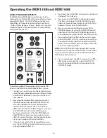
in any optional headphones plugged in to the PHONES 

connector located in the front panel jack field. If the 

AFL/PFL MODE switch, located in the master section, is 

switched out, the signal is sent pre fader, so you can hear 

the signal regardless of the position of the channel vol-

ume Fader. This allows you to listen to a channel by itself: 

(let's say) to see if an artist is out of tune, or to cue  up a 

channel without having to play it through the main PA 

speakers.  If the AFL/PFL MODE switch is switched in, the 

signal is sent post fader, the signal you hear is dependant 

on the position of the channel volume Fader. This allows 

you to hear if there is any distortion on a channel added 

by the level of the channel fader.

 11- SOLO LED

The MDR1248 and MDR1688’s Mono Input channels 

include a SOLO LED which, when illuminated, indicates 

that the signal is assigned to the SOLO bus.  

12 - PEAK LED

The MDR1248 and MDR1688’s MIC/LINE pre-amp also 

includes a PEAK LED which, when illuminated, indicates 

that the signal is peaking or overloading.  To reduce dis-

tortion, lower the GAIN control to keep this LED from stay-

ing on. 

13 - CHANNEL LEVEL

The MDR1248 and MDR1688’s LEVEL control knobs are 

used to adjust the overall channel volume.  

STEREO INPUT CHANNEL SECTION

The MDR1248 and MDR1688 feature stereo input chan-

nels for connected stereo line level devices like keyboards 

and drum machines, as well as the outputs from effects 

processors and digital guitar modelers. The MDR1248 has 

four sets of stereo inputs which make up channels 5/6, 

7/8, 9/10 and 11/12, while the MDR1688 has four sets of 

stereo inputs which make up channels 9/10, 11/12, 13/14 

and 15/16. The Stereo input channels have a four-band 

fixed equalizer and AUX 1 and 2 sends and are laid out the 

same as the mono inputs. The following section details 

the stereo input controls:

14- GAIN  switch

The  MDR1248 and MDR1688’s pre-amp stage has a vari-

able GAIN switch with a range of -10 to +4dB on the ste-

reo LINE input.   

15 - LOW/LOW MID/HIGH MID/HIGH - Channel 

Equalizer

The MDR1248 and MDR1688 Stereo input channels fea-

ture a 4-band equalizer allowing you to adjust the high, 

mid, and low frequencies independently on each channel. 

The stereo channel equalizer is laid out like a mono input 

on the control panel input strip, but internally, the equal-

izer is effecting a stereo signal path. The channel’s fre-

quency response is flat when the knobs are in the “12:00” 

position. Rotating the knob towards the right will boost 

the corresponding frequency band by 15dB, and rotating 


Controls and Functions

it towards the left will cut the frequency by 15dB. The fre-

quency centers, range of boost or cut, and equalizer type 

for each band are as follows:
High: 12kHz +/- 15dB shelving type
High Mid: 3kHz +/- 15dB peaking type
Low Mid: 500Hz +/- 15dB peaking type
Low: 80Hz +/- 15dB shelving type

Summary of Contents for MDR1248

Page 1: ...MDR Series Mixers TWELVE AND SIXTEEN CHANNEL MIXER WITH 24 bit DSP EFFECTS ...

Page 2: ...rtant Safety Instructions 1 Please read all instructions before operating the unit 2 Keep these instructions for future reference 3 Please heed all safety warnings 4 Follow manufacturers instructions 5 Do not use this unit near water or moisture 6 Clean only with a damp cloth 7 Do not block any of the ventilation openings Install in accordance with the manufacturers instructions 8 Do not install n...

Page 3: ...almente o si ha caído al suelo Instrucciones de seguridad Istruzioni di Sicurezza ATTENZIONE per ridurre il rischio di incendio o di scariche elettriche non esponete questo apparecchio a pioggia o umidità Per ridurre il pericolo di scariche elettriche evitate di rimuoverne il coperchio o il pannello posteriore Non esistono all interno dell apparecchio parti la cui regolazione è a cura dell utente ...

Page 4: ...ight 2006 Samson Technologies Corp Printed September 2006 v1 1 Samson Technologies Corp 45 Gilpin Avenue Hauppauge New York 11788 8816 Phone 1 800 3 SAMSON 1 800 372 6766 Fax 631 784 2201 www samsontech com ...

Page 5: ...ION 15 Operating the MDR1248 and MDR1688 16 USING THE DIGITAL EFFECTS 16 SENDING AN INDEPENDENT MIX TO THE MONITOR SPEAKERS 17 USING THE CHANNEL INSERT JACKS 17 USING AN EXTERNAL EFFECT 18 PLAYING BACK A CD USING 2T TO MIX 18 RECORDING A MIX FROM THE MDR1248 and MDR1688 18 MDR1248 and MDR1688 System Set Ups 19 MDR1248 and MDR1688 LIVE SOUND SET UP 19 MDR1248 and MDR1688 RECORDING SET UP 20 MDR1248...

Page 6: ...cement and commercial installations the MDR1248 and MDR1688 are ideal mixer solutions offering big sound in a compact package Introduction In these pages you ll find a detailed description of the features of the MDR1248 and MDR1688 mixers as well as a description of their front and rear panels step by step instructions for their setup and use and full specifications You ll also find a warranty car...

Page 7: ...hannel equalizer with sweepable mids on the mono input channels along with four band fixed equalizer on the stereo channels provide precise and musical results in contour ing the tone of any signal Two Auxiliary Sends for built in or external effects on stage monitor mix or headphone mixing For added flexibility AUX 1 can be con figured as a Pre or Post fader send High quality low noise discrete m...

Page 8: ... 38 37 39 21 40 41 42 43 44 45 46 47 48 50 51 52 53 54 55 56 57 58 49 59 Front Panel Layout ...

Page 9: ...ensitiv ity from 10dB when the switch is pressed in to 4dB when this switch is out 21 RIGHT LINE 1 4 inch phone input connector for the right line input for the stereo channels 22 LEFT MONO LINE 1 4 inch phone input connec tor for the Left Line input for the stereo channels or a mono input 23 ALT 3 4 OUTPUTS jacks Balanced 1 4 inch phone connectors carrying the signal from the ALT 3 4 bus 24 CONTR...

Page 10: ...Controls the channel s position between left and right of the stereo inputs REAR PANEL A POWER Switches on the MDR1248 and MDR1688 s main power B PHANTOM Engages the 48 Volt Phantom power supply to microphone pre amps C AC ADAPTOR INLET Connect External AC power supply here 50 AUX RETURN 1 Used to mix in the level of AUX Return 1 51 AUX RETURN 2 Used to mix in the level of AUX Return 2 52 AUX RETU...

Page 11: ...st the high mid range and low frequencies independently on each channel The fre quency centers range of boost or cut and equalizer type for each band are described in the following section HF HIGH FREQUENCY 12kHz 15dB Shelving type The channel s HIGH frequency response is flat when the knob is in the 12 00 position Rotating the knob towards the right will boost the channel s high frequency respons...

Page 12: ...uses to send the signal When the PRE POST switch is set to PRE the signal feeding AUX 1 is sent before the fader so the channel Fader has no effect on that level This is the normal setting when using AUX 1 as Controls and Functions a monitor send When the PRE POST switch is set to POST the signal feeding AUX 1 is sent after the fader so the channel Fader has an effect on that level meaning the Aux...

Page 13: ...ls for connected stereo line level devices like keyboards and drum machines as well as the outputs from effects processors and digital guitar modelers The MDR1248 has four sets of stereo inputs which make up channels 5 6 7 8 9 10 and 11 12 while the MDR1688 has four sets of stereo inputs which make up channels 9 10 11 12 13 14 and 15 16 The Stereo input channels have a four band fixed equalizer an...

Page 14: ...l Controls and Functions Auxiliary Busses 16 18 The MDR series include two auxiliary signal paths or buses that can be used to create independent mixes for sending to the internal or external effects processors or to an external monitor system The signal flow from these buses start by sending the signal from each individual channel which is set with one of the auxiliary control knobs Then the mix ...

Page 15: ...ack 32 ALT 3 4 Level control knob Use this control knob to set the level of the mix created from the channels assigned to the 3 4 bus The ALT 3 4 level control will control the level of the signal being sent to the 3 4 Output jacks When the Master ALT 3 4 switch 43 is switched in the ALT 3 4 level control will con trol the level of the ALT 3 4 mix that is heard in the Main Left and Right mix Remem...

Page 16: ...d MAIN LEVEL fader Control Room and Headphone Assign Switches The next three switch functions are used to select addi tional sources that can be heard in the headphones and sent to the Left and Right Control Room Outputs 42 MAIN MIX switch The MAIN MIX switch routes the Left Right MAIN mix bus to the CONTROL ROOM PHONES outputs Use the Left Right MAIN MIX Level faders 48 and PHONES level fader 49 ...

Page 17: ...a 1 4 inch connector for line level signals and an XLR connector for the MIC signals Channels 5 6 through 11 12 on the MDR1248 and channels 9 10 through 15 16 on the MDR1688 are stereo inputs providing a pair of 1 4 inch connectors for line level inputs By using the GAIN control on the mono channels you can connect a variety of signal sources from microphones to line level devices such as synthesi...

Page 18: ...by connecting the output to an external effects device MDR1248 and MDR1688 Input and Output Connections L AUX RETURN 2 LEFT RIGHT The AUX RETURN 2 LEFT RIGHT are stereo inputs that are generally used to connect the outputs of an effects proces sor but can also accept the signal from any line level source like a keyboard recorder and even another mixer The signal connected to the AUX RETURN 2 LEFT ...

Page 19: ... the LEVEL SET function When the PFL is switched on you ll see the LEVEL SET LED is illuminated and the channel s input level will now be displayed on the Main VU meter 3 Switch on the power of any peripheral devices and then power up the MDR1248 and MDR1688 NOTE It is important to remember the Golden Rule of audio LAST ON FIRST OFF Translated this means that when turning on your system you should...

Page 20: ... are set up in groups by the types of effects 3 Once you have selected the desired effects preset raise the AUX 2 DSP control on the channels you wish to apply the digital effect to Operating the MDR1248 and MDR1688 4 Next locate the AUX SEND 2 knob and turn it about to a little past 5 or half way 5 Now use the AUX RETURN 2 control knob to adjust the effects return level The AUX RETURN 2 control k...

Page 21: ...nnel AUX1 levels to achieve a cleaner mix In order to get the most gain from your monitor mix use an exter nal graphic equalizer like a Samson S curve 131or D2500 digital EQ with feedback control to cut out any frequen cies that cause feedback 6 If you want to add effects from the internal effect processor or the effects from an external proces sor connected to the AUX RETURN 2 inputs engage the A...

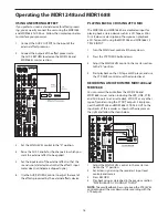
Page 22: ...n to the 0 position 2 Set a clean signal using the recorder s input level controls and meters 3 Press RECORD 4 Play back using as described in the previous section PLAYING BACK A CD USING 2T TO MIX NOTE To avoid feedback be sure to keep the 2TK LEVEL control knob all the way down while recording with the 2TK outputs Operating the MDR1248 and MDR1688 USING AN EXTERNAL EFFECT If you prefer to use an...

Page 23: ... which is driving 2 monitor speakers For inputs two microphones are con nected to channels 1 and 2 s low impedance inputs and the output of the Bass Direct Box is also connect ed to the low impedance input on channel 4 The Keyboards as well as the Lead and Rhythm Guitar signal processor s out puts are connected to the MDR1248 and MDR1688 s line inputs MDR1248 and MDR1688 s AUX SEND 1 connected to ...

Page 24: ...eadphone mix sent to a Samson S phone head phone amp For inputs two microphones are connected to channel 1 and 2 s low imped ance inputs and the output of the Bass Direct Box is also connected to the low imped ance input on channel 4 The Keyboards as well as the Lead and Rhythm Guitar signal processor s outputs are con nected to the MDR1248 and MDR1688 s line inputs MDR1248 and MDR1688 RECORDING S...

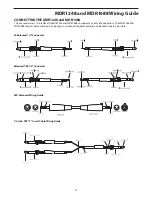
Page 25: ...HE MDR1248 and MDR1688 The are several ways to interface the MDR1248 and MDR1688 to support a variety of applications The MDR1248 and MDR1688 features balanced inputs and outputs so connecting balanced and unbalanced signals is possible Balanced TRS 1 4 Connector 1 4 inch TRS Y Insert Cable Wiring Guide ...

Page 26: ...l 15dB 3kHz Low Mid bell 15dB 500Hz Low shelving 15dB 80Hz Main Mix Section Noise Bus noise Levels full down 100dBr ref 4dBu Level set to 0 dB 90dBr ref 4dBu Max output 28dBu balanced XLR 22dBu impedance balanced 1 4 jacks 3 4 Output Section Noise Bus noise Levels full down 100dBr ref 4dBu Level set to 0 dB 90dBr ref 4dBu Max output 22dBu impedance balanced 1 4 jacks Control Room Output Section No...

Page 27: ......

Page 28: ...Samson Technologies Corp 45 Gilpin Avenue Hauppauge New York 11788 8816 Phone 1 800 3 SAMSON 1 800 372 6766 Fax 631 784 2201 www samsontech com ...

Reviews: