2
850 819 R.11/09
Samson Corporation • One Samson Way • N.C. 28778 Swannanoa • Phone: 00 1 828-686 8511 • Fax: 00 1 828-686 8533
Installation / Instalación
El enrollador puede instalarse directamente sobre la superficie
de montaje, una base de fijación (fig.A) o un soporte pivotante
(fig. B). El brazo de salida tiene varias posiciones para un
adecuado funcionamiento.
•
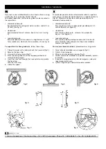
PERPENDICULAR REELING
Para montaje en techo o sobre pared por debajo de 2.5
metros (8 pies) (ver figura 2).
•
SIDE REELING
Para montaje sobre suelo , columna, foso, depósito,
banco… (ver figura 3).
•
TANGENTIAL REELING
Para montaje sobre pared por encima de 2.5 metros (8
pies). También adecuado para montaje sobre unidades
móviles. (ver figura 4).
Para mover el brazo de salida,
el procedimiento es el siguiente:
1 . Fijar el disco del enrollador con un sargento (fig C).
2 . Quitar el tope manguera.
3 . Aflojar los tornillos del brazo superior (fig 5).
4 . Colocar el brazo del enrollador en la posición deseada y apretar
los tornillos.
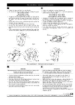
5 . Introducir la manguera por la salida de manguera y colocar el
tope manguera de nuevo.
6 . Quitar el sargento para liberar el disco del enrollador.
E
Hose reel can be installed directly onto a fixed surface or using
a plate (fig. A) or a pivoting bracket (fig. B).
For optimal operation; the hose arm guide can be mounted in
these positions:
•
PERPENDICULAR REELING
Recommended for ceiling and wall or column under 2.5 m
(8 feet) (see fig. 2).
•
SIDE REELING
Recommended for wall, column, bench, tank, etc (see fig
3).
•
TANGENTIAL REELING
Recommended for wall or column at a height above 2.5 m (8
feet), mobile units, lube truck, tank assemblies, etc. (see fig. 4).
To reposition the hose guide arm
, follow these steps:
1. Clamp the spool with c-clamp to lock the hose reel (fig C)
2. Remove the hose stop.
3. Unscrew the fixing screws (fig 5)
4. Place the hose guide arm in the required position and
screw the fixing screws.
5. Insert the hose reel through the hose outlet and assemble
the hose stop.
Affix the hose stop.
6. Unlock the spool.
EN
fig. 2
fig. 3
fig. 4
fig. A
fig. B
fig. C
fig. 5


