18
EB 8359-1 EN
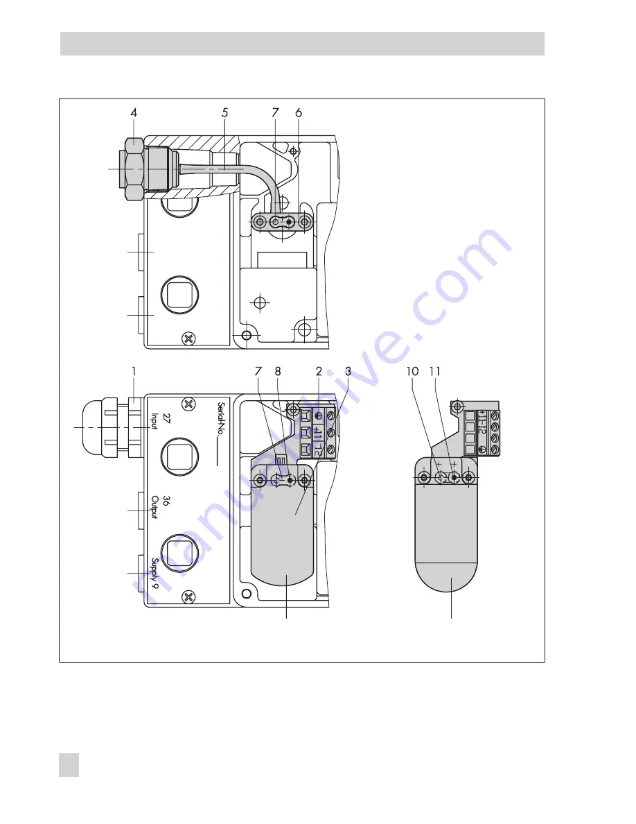
Converting a pneumatic positioner
Fig. 14 · Converting the positioner
1
Cable gland
2
Printed circuit board
3
i/p module
4
Connecting nipple
5
Hose
6
Connecting plate
7
Sealing element
Page 1: ...Pneumatic Positioner Type 4765 Fig 1 Type 4765 Positioner Mounting and Operating Instructions EB 8359 1 EN Edition April 2008...
Page 2: ...ner and actuator 11 4 1 1 Determining reversing the operating direction 11 4 2 Starting point and input signal reference variable 12 4 3 Setting the positioner at the valve 14 4 3 1 Setting the air de...
Page 3: ...due to their specialized training their knowledge and experience as well as their knowledge of the applicable standards 4 Any hazards that could be caused by the process medium the operating pressure...
Page 4: ...ge spring 1 travel 15 mm 1 Range spring 2 travel 30 mm split range 15 mm 2 Range spring 3 travel 60 mm split range 30 mm 3 Pneumatic connections ISO 228 1 G 1 18 NPT 3 Temperature range Standard 0 Low...
Page 5: ...nal band Xp at 1 4 bar supply air 1 to 3 with spring 1 or 2 1 to 1 5 with spring 3 Air consumption in steady state Xp 1 With 1 4 bar supply air 0 13 mn h With 6 bar supply air 0 33 mn h Air output cap...
Page 6: ...erates according to the force balance principle In this way the stroke of the actuator stem or the plug stem controlled variable x is transmitted to the lever 1 and the range spring 6 by the plate 20...
Page 7: ...l and the nominal reference input span It can be exchanged EB 8359 1 EN 7 Design and principle of operation 1 1 1 2 2 1 20 4 6 8 9 9 1 10 2 10 10 1 11 pst Output 36 Supply 9 pe Input 27 6 8 9 9 1 12 2...
Page 8: ...1 Attachment to valves with cast yokes 1 Fasten the plate 20 to the stem connec tor clamps 22 of the valve using the screws 21 2 Unscrew the positioner cover and secure the device to the valve yoke u...
Page 9: ...half the valve travel 3 Screw tight the support and clamping plate 4 Mount the positioner to the support using the mounting screw 15 Make sure that the pin 2 is led inside the wire strap and therefor...
Page 10: ...ch range is written on the nameplate as spring range or signal pressure range depending on the type of actuator FA actu ator stem extends or FE actuator stem re tracts or a symbol indicates the operat...
Page 11: ...creases the signal pressure pst can either be increasing direct operating direction or decreasing reverse operating direction The same applies to a decreasing input sig nal the output pressure either...
Page 12: ...point and input signal reference variable The attached lever and the installed range spring of the positioner correspond to the rated valve travel and the reference variable input signal according to...
Page 13: ...ce input span and the final value is adjusted by the pin 2 EB 8359 1 EN 13 Operation Fig 11 Standard operation Reference variable Input signal Closed Travel Open Fig 12 Split range operation two valve...
Page 14: ...On setting the Xp restriction observe the re lationship with the supply air pressure as in dicated in Fig 13 The preset value of Xp should read approximately 3 3 Check the plug stem s tendency to osc...
Page 15: ...ange watch the travel indicator at the valve If the upper range value is in correct the pin 2 must be moved as fol lows in order to correct the signal 4 Move pin to End of lever to increase travel Piv...
Page 16: ...n the zero adjustment screw 4 until the pressure gauge indicates the re quired signal pressure see also section 3 1 2 In case there is no pressure gauge avail able set the starting point to 0 97 bar i...
Page 17: ...striction and the filter 8 are situated on the right side above the innermost of the two housing holes supply air when the module dashed line in Fig 14 is installed 5 Secure the module and the printed...
Page 18: ...18 EB 8359 1 EN Converting a pneumatic positioner Fig 14 Converting the positioner 1 Cable gland 2 Printed circuit board 3 i p module 4 Connecting nipple 5 Hose 6 Connecting plate 7 Sealing element...
Page 19: ...kit for valves with rod type yokes acc to NAMUR for 18 to 35 mm rod diameters 1400 5745 1400 5745 and 1400 5342 Spare parts assortment with seals and diaphragms 1400 6792 Spare parts assortment with...
Page 20: ...8359 1 EN Dimensions in mm Useable lever length I 40 to 127 mm with 40 to 200 mm lever extension Pneum connection ISO 228 1 G or 18 NPT 157 Tapped hole G 1 8 for G threaded connection or 1 8 NPT for...
Page 21: ...EB 8359 1 EN 21...
Page 22: ...22 EB 8359 1 EN...
Page 23: ...EB 8359 1 EN 23...
Page 24: ...SAMSON AG MESS UND REGELTECHNIK Weism llerstra e 3 60314 Frankfurt am Main Germany Phone 49 69 4009 0 Fax 49 69 4009 1507 Internet http www samson de EB 8359 1 EN S Z 2012 01...