5-2
EB 3756 EN
Installation
3. Use a cap screw to fasten the booster
valve to the yoke/support.
5.3.2
Attachment to rotary
actuators
Î
See section 5.6 for required accessories
Type 3756-00
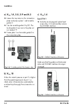
1. Check the seating of the O-rings on the
NAMUR interface and that of the coded
screw. Use a coded screw to determine
the direction of action of the rotary actu-
ator at the connecting flange.
2. Fasten the booster valve to the rotary ac-
tuator using two screws.
32
24
B
A
¼"
2
M5
8
12
DIN EN ISO 228-1
Sectional view A-B
Coded screw
Fig. 5-1:
NAMUR interface ¼"
5.4
Pneumatic connection
The air connections are designed as thread-
ed holes with G
1
/
8
(
1
/
8
NPT), G ¼ (¼ NPT),
G ½ (½ NPT) or G 1 (1 NPT) threads de
-
pending on the device version.
Î
Run and attach the connecting lines and
screw joints according to good profes-
sional practice.
Î
Check the connecting lines and screw
joints for leaks and damage at regular
intervals and repair them.
Î
The K
VS
coefficient of an upstream pres
-
sure reducing valve must be at least 1.6
times larger than the K
VS
coefficient of
the device.
Port labeling K
VS
2.0 and 4.3
Inscription
Function
4
Supply air
8
Control pressure (with
pneumatic actuation only)
9
External pilot supply (only when
a pilot valve is used)
3/5
Output
Summary of Contents for 3756
Page 1: ...Translation of original instructions EB 3756 EN Edition April 2023 Type 3756 Booster Valve...
Page 12: ...2 4 EB 3756 EN...
Page 24: ...3 12 EB 3756 EN...
Page 34: ...6 2 EB 3756 EN...
Page 36: ...7 2 EB 3756 EN...
Page 38: ...8 2 EB 3756 EN...
Page 42: ...10 2 EB 3756 EN...
Page 44: ...11 2 EB 3756 EN...
Page 46: ...12 2 EB 3756 EN...
Page 48: ...13 2 EB 3756 EN...
Page 50: ...14 2 EB 3756 EN...
Page 51: ...EB 3756 EN 14 3...
Page 52: ...14 4 EB 3756 EN...
Page 54: ...15 2 EB 3756 EN...
Page 55: ......


