background image

28 


EB 8395 EN

Operating the positioner

Canceling initialization

The initialization can be canceled by press

-

ing  .


ESC blinks on the display.


Press   to confirm.

This code must be confirmed by touching 

Otherwise, the code remains active.

Initial state 1:


Positioner has 

not

 been initialized

The positioner goes to the fail-safe position 

after the initialization process has been can

-

celed.

Initial state 2:


Positioner is initialized

On canceling a new initialization process, 

the positioner returns to closed-loop opera-

tion. The settings of the previous initialization 

are used.

A new initialization can be started directly 

afterwards.

7.10 Zero calibration

In case of inconsistencies in the closed posi-

tion of the valve (e.g. with soft-seated plugs), 
it might be necessary to recalibrate zero. En

-

able configuration as described in sec

-

tion 7.2.
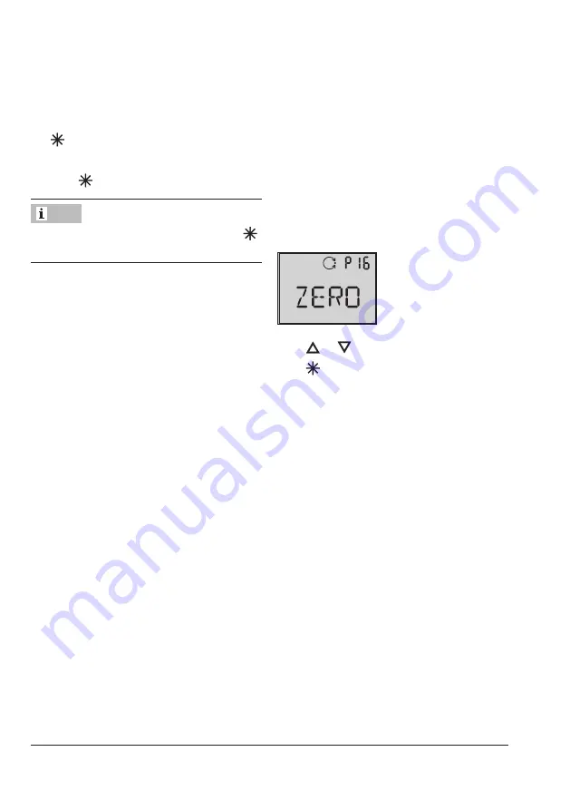
Start the zero calibration by activating Code 
P16 as follows:

Press 

 or 

 until Code 

P16

 appears.

Press 

 and hold for six seconds. 

6-5-4-3-

2-1-

 is counted down on the display.

Zero calibration starts, the display blinks!

The positioner moves the control valve to the 

CLOSED position and recalibrates the inter

-

nal electric zero point.
When the zero calibration has been success

-

fully completed, the positioner returns to 

closed-loop operation (display with status in

-

dication).

Note

Summary of Contents for 3724

Page 1: ...Translation of original instructions EB 8395 EN Firmware version 1 01 Edition October 2018 Type 3724 Electropneumatic Positioner Type 3724 Positioner cover removed...

Page 2: ...fter sales Service Department aftersalesservice samson de The mounting and operating instructions for the devices are included in the scope of delivery The latest documentation is available on our web...

Page 3: ...ions 16 5 1 1 Supply pressure 16 5 2 Electrical connections 18 5 2 1 Accessories 18 5 2 2 Selecting cables and wires 19 5 2 3 Cable entry 19 6 Operation 20 6 1 Operating controls 20 7 Operating the po...

Page 4: ...shipment 31 8 2 Firmware update 31 9 Malfunction 32 9 1 Error codes 33 9 2 Emergency action 34 10 Decommissioning and removal 35 10 1 Decommissioning 35 10 2 Removing the positioner 35 10 3 Disposal...

Page 5: ...er is not suitable for the following applications Use outside the limits defined during sizing and by the technical data Furthermore the following activities do not comply with the intended use Use of...

Page 6: ...eumatic actuator as a result of the supply pressure level it must be restricted using a suitable supply pressure reducing station Responsibilities of the operator The operator is responsible for prope...

Page 7: ...t sequence during start up The positioner can only work properly if the mounting and start up are performed in the prescribed sequence Perform mounting and start up as described in section 16 in page...

Page 8: ...atic destruction limit of 32 V Malfunction due to initialization not yet completed The initialization causes the positioner to be adapted to the mounting situation After ini tialization is completed t...

Page 9: ...Reference variable 5 Supply 2 2 Article code Positioner Type 3724 0 0 0 0 0 0 x 0 0 0 0 0 Housing material Housing 1 4409 Cover 1 4404 0 Surface finish Micro bead blasted 1 Polished Ra 0 6 m 2 Permiss...

Page 10: ...ange This change is sensed by the sensor 2 The elec tronics unit determines the current valve posi tion from this information The position of the valve is transmitted to the microcontroller 4 over its...

Page 11: ...6 7 8 10 1 w 9 x y 2 5 A2 A1 12 1 Control valve 2 Sensor 3 A D converter 4 Microcontroller 5 D A converter 6 i p converter 7 Air capacity booster 8 Pressure regulator 9 Flow regulator 10 Volume restri...

Page 12: ...t 10 K below the lowest ambient temperature to be expected Signal pressure output 0 bar up to the supply pressure minus 0 4 bar Can be limited to approx 2 3 bar by software Characteristic Three select...

Page 13: ...max Version Reverse polarity protection galvanic isolation Adjustment range 0 to 100 see section 7 7 on page 26 Step size 0 5 Static destruction limit 32 V Signal state No response Non conducting hig...

Page 14: ...esign and principle of operation 3 2 Dimensions in mm Actuator Piston d Type 3379 63 mm 69 mm 90 mm 94 mm 108 285 135 d 130 Fig 2 Dimensional drawings of Type 3724 Positioner with Type 3379 Pneumatic...

Page 15: ...g impact Protect the positioner against moisture and dirt Observe transport temperature depend ing on the permissible ambient tempera ture see technical data in section 3 1 4 3 Storage Risk of positi...

Page 16: ...ICE Note 5 1 Pneumatic connections The Type 3724 Positioner is delivered ready mounted on the Type 3379 Pneumatic Piston Actuator The pneumatic connections of the positioner are connected internally t...

Page 17: ...For tight closing valves the maximum signal pressure pstmax is roughly estimated as fol lows pstmax F d p bar 4 A d Seat diameter cm p Differential pressure across the valve bar A Actuator area cm F U...

Page 18: ...described in sec tion 5 2 3 Incorrect assignment of the terminals will damage the positioner and will lead to mal function Connect the electrical wiring to the position er according to the prescribed...

Page 19: ...of 6 to 12 mm The cage clamp terminals hold wire cross sections of 0 2 to 1 5 mm Unscrew the cover and remove it To unlock the cage clamp terminals place a slotted screwdriver on the plastic part Fig...

Page 20: ...ange to Code P0 or wait three minutes until the display re turns automatically to P0 The icon on the display indicates that the changed parameter settings have not yet been saved in the non volatile m...

Page 21: ...EB 8395 EN 21 Operation Cover Pick up rod Positioner Actuator Pushbuttons Terminals Vent plug Fig 6 Type 3724 Positioner mounted on Type 3379 Pneumatic Piston Actuator...

Page 22: ...e of 10 mm If the fault indication icon is displayed press or until ERR is displayed to view the relevant E0 to E15 error code s see code list in section 33 on page 9 1 7 Operating the positioner The...

Page 23: ...he mechanical stops risk of me chanical damage the positioner vents the actuator and the valve moves to its fail safe position S displayed together with E8 error code 7 1 Adapting the display The disp...

Page 24: ...s re quire a restricted air flow rate Setting to MIN Actuators with a transit time 0 4 s do not require the air flow rate to be restrict ed Setting to MAX Intermediate settings are not permitted Malfu...

Page 25: ...ective after the posi tioner has been re initialized 7 5 Entering the direction of action The direction of action P7 is set to increas ing increasing by default For checking purposes After successfull...

Page 26: ...nd press to confirm the value The switching values for P12 and P13 must be adjusted at least 5 from one another It is not possible to enter switching values that are less than 5 from one another 7 8 S...

Page 27: ...set in Code P4 is only limited during initialization However it might be exceeded in closed loop control when the control signal is higher than 20 mA Start initialization by activating Code P15 as fol...

Page 28: ...lization are used A new initialization can be started directly afterwards 7 10 Zero calibration In case of inconsistencies in the closed posi tion of the valve e g with soft seated plugs it might be n...

Page 29: ...rs Press and hold for six seconds 6 5 4 3 2 1 is counted down on the display P17 blinks The manual set point is indicated on the dis play of an initialized positioner If the positioner has not yet bee...

Page 30: ...and re turn to the display showing the status indica tion 7 12 Reset A reset causes an initialization to be undone and all parameters settings are reset to the default settings see code list in sec t...

Page 31: ...for repair Proceed as follows to return devices to SAMSON 1 Put the control valve out of operation See associated valve documentation 2 Fill in the Declaration on Contamination The declaration form c...

Page 32: ...tance a travel has been entered in Code P4 nominal range which is larger than the maximum valve travel possible the initialization process would be interrupted E2 error code because the rated travel w...

Page 33: ...not identical operational error Adjusted and displayed valves are not identical to the INIT values as the parameters were changed after initialization 3 Recommended action Reset parameters or perform...

Page 34: ...pply air mounting blocked 2 Recommended action Check supply air positioner mounting and mA input signal Re initialize the positioner E8 x range Pick up rod in range of the end stops 1 Recommended acti...

Page 35: ...ws 1 Disconnect and lock the air supply and signal pressure 2 Open the positioner cover and discon nect the wires for the control signal 10 2 Removing the positioner 1 Disconnect the wires for the con...

Page 36: ...an reach the After sales Service De partment at aftersalesservice samson Addresses of SAMSON AG and its subsid iaries The addresses of SAMSON AG its subsid iaries representatives and service facilitie...

Page 37: ...ine the relation ship between the input variable and the position of the actuator stem 0 Linear 1 Equal percentage 2 Reverse equal percentage P6 Reference variable 4 to 20 mA SRLO SRHI For split range...

Page 38: ...ignal P15 Start initialization Press button to cancel the initialization process As a result the valve moves to the fail safe position After a power supply failure during initialization the positioner...

Page 39: ...EB 8395 EN 39...

Page 40: ...2018 10 10 English SAMSON AKTIENGESELLSCHAFT Weism llerstra e 3 60314 Frankfurt am Main Germany Phone 49 69 4009 0 Fax 49 69 4009 1507 samson samson de www samson de EB 8395 EN...

Reviews:

Related manuals for 3724