background image

9-6  

EB 8026 EN

Servicing

14

25
21

2

33

AB

A

B

9

A26/27

5

4

1

2

15

8

10

A8

A7

141

17

84

A

AB

B

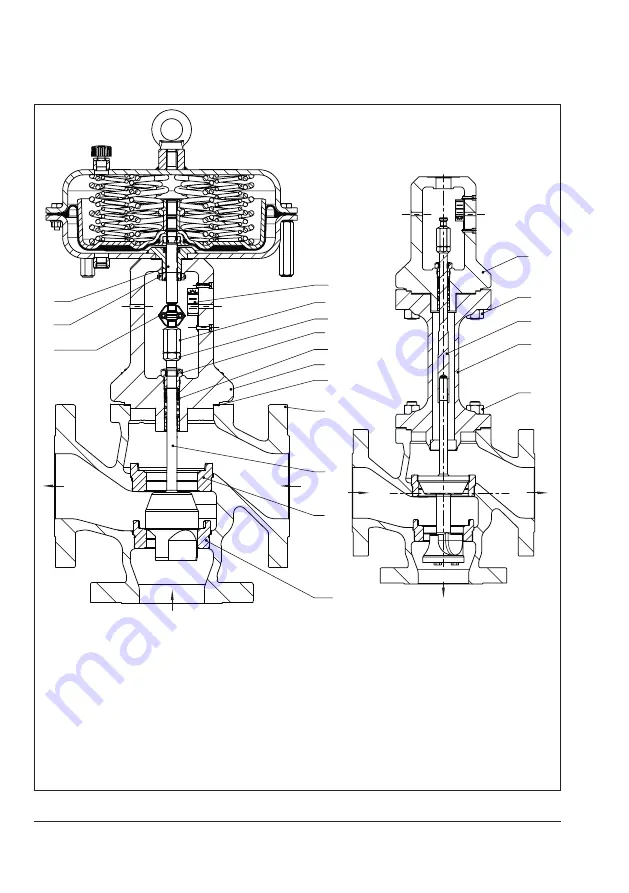
1 Body

2

Flange

4

Top seat

5

Plug (with plug stem)

8

Threaded bushing 

(packing nut)

9

Stem connector nut

10 Lock nut
14 Nuts
15 Packing
17 Body gasket
21 Insulating section

25

Plug stem extension

33 Nuts

84 Travel indicator scale

141 Bottom seat

A7 Actuator stem
A8 Ring nut

A26/


27 Stem connector clamps

Fig. 9-1: 

Standard version of Type 3244 (as mixing valve) with Type 3271 Actuator (left) and 

Type 3244 (as diverting valve) in version with insulating section (right)

Summary of Contents for 3244

Page 1: ...ructions EB 8026 EN Edition May 2020 Type 3244 Valve DIN and ANSI versions In combination with an actuator e g a Type 3271 or Type 3277 Pneumatic Actuator Type 3244 Valve with Type 3271 Actuator left...

Page 2: ...If you have any questions about these instructions contact SAMSON s After sales Service aftersalesservice samsongroup com Documents relating to the device such as the mounting and operating instructi...

Page 3: ...gs 3 3 3 3 Accessories 3 4 3 4 Technical data 3 4 4 Shipment and on site transport 4 1 4 1 Accepting the delivered goods 4 1 4 2 Removing the packaging from the valve 4 1 4 3 Transporting and lifting...

Page 4: ...9 5 9 4 1 Replacing the gasket 9 7 9 4 2 Replacing the packing 9 8 9 4 3 Replacing the seat and plug 9 10 9 5 Ordering spare parts and operating supplies 9 10 10 Decommissioning 10 1 11 Removal 11 1...

Page 5: ...as well as possible uses Reasonably foreseeable misuse The control valve is not suitable for the following applications Use outside the limits defined during sizing and by the technical data Use outs...

Page 6: ...upon supply air or control signal failure The fail safe action of the actuator is the same as its direction of action and is specified on the nameplate of SAMSON actuators Warning against residual haz...

Page 7: ...n Pressure Equipment Direc tive 2014 68 EU and the Machinery Directive 2006 42 EC Valves with a CE marking have a declaration of conformity which includes information about the applied conformity asse...

Page 8: ...ding on the process medium valve components and pipelines may get very hot or cold and cause burn injuries Allow components and pipelines to cool down or heat up Wear protective clothing and safety gl...

Page 9: ...any stored energy in the actuator e g spring compression See associated actuator documentation Risk of personal injury due to preloaded springs Valves in combination with pneumatic actuators with prel...

Page 10: ...isk of valve damage due to contamination e g solid particles in the pipeline The plant operator is responsible for cleaning the pipelines in the plant Flush the pipelines before start up Risk of valve...

Page 11: ...terial Unsuitable lubricants may corrode and damage surfaces Only use lubricants approved by SAMSON u AB 0100 Risk of the process medium being contaminated through the use of unsuitable lubricants and...

Page 12: ...Warning Meaning of the warning Location on the device Warning against moving parts There is a risk of injury to hands or fingers through the stroking movement of the actuator and plug stem if they are...

Page 13: ...Pressure rating DIN PN ANSI CL JIS K 8 Order number item 10 Flow coefficient DIN KVS ANSI CV 11 Characteristic LIN linear NO NC on off service 12 Seat plug seal ME metal seal ST metal base material w...

Page 14: ...the valves have an item number written on them You can contact us stating this item number to find out which material is used Additionally a seat code is used to identify the trim material This seat c...

Page 15: ...y the arrow A rise in signal pressure causes the force acting on the diaphragm in the actuator to increase The springs are compressed Depending on the selected direction of action the actuator stem re...

Page 16: ...esign and principle of operation Fig 3 1 Type 3244 Valve as mixing valve with Type 3271 Pneumatic Actuator Fig 3 2 Type 3244 Valve as diverting valve AB A B 141 5 4 14 9 A26 27 5 4 1 2 15 8 10 A8 A7 1...

Page 17: ...d by another pneumatic actuator in a different size but with the same travel Observe the maximum permissible actu ator force If the travel range of the actuator is larger than the travel range of the...

Page 18: ...d by the plant and its operating conditions 3 3 Accessories Information Sheet u T 8350 3 4 Technical data The nameplates on the valve and actuator provide information on the control valve ver sion See...

Page 19: ...N version Valve DN 15 20 25 32 40 50 65 80 100 125 150 L mm 130 150 160 180 200 230 290 310 350 400 480 H1 mm 235 270 360 375 H2 mm 70 80 85 100 105 120 130 140 150 200 210 Table 3 2 Dimensions of the...

Page 20: ...wings L H1 H2 H4 Standard version of Type 3244 Type 3244 with insulating section or bellows seal Table 3 4 Weights of Type 3244 Valve Without actuator Valve DN 15 20 25 32 40 50 65 80 100 125 150 NPS...

Page 21: ...ta section 4 2 Removing the packaging from the valve Observe the following sequence Do not open or remove the packaging until immediately before lifting to install the valve into the pipeline Leave th...

Page 22: ...ings to the actuator handwheel or any other parts Observe lifting instructions see sec tion 4 3 2 A swivel hoist can be screwed into SAMSON actuators with a female thread on the top diaphragm case in...

Page 23: ...sure the slings can be removed from the valve once it has been installed into the pipeline Prevent the control valve from tilting or tipping over Do not leave loads suspended when in terrupting work...

Page 24: ...ecure the valve in the stored position against slipping or tipping over Do not damage the corrosion protection paint surface coatings Repair any damage immediately Protect the control valve against mo...

Page 25: ...EB 8026 EN 4 5 Shipment and on site transport...

Page 26: ...4 6 EB 8026 EN...

Page 27: ...ditions and are intended as recommendations Contact SAMSON if the lengths are significantly shorter than the recommended lengths To ensure that the valve functions properly proceed as follows Observe...

Page 28: ...and implementing a suitable support or suspension of the installed control valve and the pipeline Depending on the valve version and mount ing position the valve actuator and pipeline must be supporte...

Page 29: ...ion FA Actuator stem extends FE Actuator stem retracts In heating applications with FA the heating medium flow is shut off in the fail safe position in cooling applications with FE cooling is maintain...

Page 30: ...unction properly Do not insulate valves mounted to com ply with NACE MR0175 requirements and which have nuts and bolts that are not suitable for sour gas environments Proceed as follows Lay out the ne...

Page 31: ...the valve and actuator must be assembled together on site Versions with V port plug In mixing valves in sizes larger than DN 25 the bottom plug is designed as V port plug To achieve the best flow con...

Page 32: ...incorrect opening of pressurized equipment or components Valves and pipelines are pressure equipment that may burst when handled incorrectly Flying projectile fragments or the release of process medi...

Page 33: ...springs Actuators with preloaded springs are under tension They can be identified by the long bolts protruding from the bottom of the actu ator Before starting any work on the actuator relieve the com...

Page 34: ...t seal properly contact our after sales service 5 5 2 Travel motion The movement of the actuator stem must be linear and smooth Apply the maximum and minimum con trol signals to check the end position...

Page 35: ...n or pneumatic valve accessories not fitted with noise reducing fittings Both can damage hearing Wear hearing protection when working near the valve Crush hazard arising from actuator and plug stem mo...

Page 36: ...sizing requirements see information under In tended use in the Safety instructions and measures section Start up putting the device back into oper ation 1 Allow the valve to cool down or warm up to re...

Page 37: ...alve ac cessories not fitted with noise reducing fit tings Both can damage hearing Wear hearing protection when working near the valve Crush hazard arising from actuator and plug stem moving Do not in...

Page 38: ...e handwheel of valves with actuators fitted with a handwheel must be in the neutral po sition during normal operation 7 2 Manual operation Valves with actuators fitted with a handwheel can be manually...

Page 39: ...pression See associated actuator documentation Diaphragm in the actu ator defective See associated actuator documentation Signal pressure too low Check the signal pressure Check the signal pressure li...

Page 40: ...Check the flange joint Replace gasket at the flanged joint see the Servic ing section or contact our after sales service 1 See the Markings on the device section Contact our after sales service for m...

Page 41: ...due to hot or cold com ponents and pipeline Valve components and the pipeline may be come very hot or cold Risk of burn injuries Allow components and pipelines to cool down or heat up Wear protective...

Page 42: ...ator Before starting any work on the actuator relieve the compression from the pre loaded springs see associated actuator documentation Risk of personal injury due to residual pro cess medium in the v...

Page 43: ...lan Our after sales service can support you in drawing up an inspection and test plan for your plant Note Tip We recommend the following inspection and testing which can be performed while the pro ces...

Page 44: ...erly Tighten the connections of the valve accessories Check to ensure that the actuator and plug stem move smoothly Version with adjustable packing 1 tighten the packing cor rectly see information und...

Page 45: ...y service work see the Removing the valve from the pipe line section The following service work can be per formed after preparation is completed Replacing the gasket see section 9 4 1 Replacing the pa...

Page 46: ...Stem connector nut 10 Lock nut 14 Nuts 15 Packing 17 Body gasket 21 Insulating section 25 Plug stem extension 33 Nuts 84 Travel indicator scale 141 Bottom seat A7 Actuator stem A8 Ring nut A26 27 Ste...

Page 47: ...the flange 2 with the body nuts 14 Tighten the nuts gradually in a crisscross pattern Observe tightening torques b Version with insulating section or bellows seal 1 Undo the body nuts 14 gradually in...

Page 48: ...other valve ver sions contact our after sales service a Standard version Standard packing PTFE 1 Undo the body nuts 14 gradually in a crisscross pattern 2 Lift the flange 2 and plug with plug stem 5 o...

Page 49: ...uts 14 Tighten the nuts gradually in a crisscross pattern Observe tightening torques 13 Screw in the threaded bushing 8 and tighten it Observe tightening torques 14 Loosely screw the lock nut 10 and s...

Page 50: ...roceed as described in Standard pack ing PTFE steps 1 to 8 2 Slide the parts of the packing over the plug stem extension in the specified or der Spring 11 Washer 12 Packing rings 16 3 Slide the seals...

Page 51: ...EB 8026 EN 9 11 Servicing...

Page 52: ...9 12 EB 8026 EN...

Page 53: ...clothing and safety gloves Risk of personal injury due to pressurized components and process medium being discharged Do not loosen the screw of the test con nection while the valve is pressurized Ris...

Page 54: ...he valve While working on the valve residual medium can flow out of the valve and depending on its properties cause personal injury e g chemical burns Wear protective clothing safety gloves respirator...

Page 55: ...lug stem by inserting objects into the yoke Before unblocking the actuator and plug stem after they have become blocked e g due to seizing up after remaining in the same position for a long time relea...

Page 56: ...ection 11 1 Removing the valve from the pipeline 1 Support the valve to hold it in place when separated from the pipeline see the Shipment and on site transport sec tion 2 Unbolt the flange joint 3 Re...

Page 57: ...fter sales Service 2 Send an e mail u retouren samsongroup com to register the return shipment including the following information Type Article number Configuration ID Original order Completed Declara...

Page 58: ...12 2 EB 8026 EN...

Page 59: ...EB 8026 EN 13 1 Disposal 13 Disposal Observe local national and internation al refuse regulations Do not dispose of components lubricants and hazardous substances together with your household waste...

Page 60: ...13 2 EB 8026 EN...

Page 61: ...quipment Directive 2014 68 EU on pages 14 2 to 14 4 Declaration of conformity in compliance with Machinery Directive 2006 42 EC for Types 3244 1 and 3244 7 Control Valves on page 14 5 Declaration of i...

Page 62: ...rged steel Geh use Schmiedestahl DN 32 100 1 Pmax T 20 C 10 bar NPS 1 4 1 Pmax T 70 F 150 psi Tout type de fluides all fluids alle Fluide Vanne de r gulation passage droit globe valve Durchgangsventil...

Page 63: ...tion des lois des Etats Membres concernant la mise disposition sur le march d quipements sous pression Directive of the European Parliament and of the Council on the Harmonization of the laws of the M...

Page 64: ...14 4 EB 8026 EN...

Page 65: ...EB 8026 EN 14 5...

Page 66: ...14 6 EB 8026 EN...

Page 67: ...ing 12 Washer 13 Stud bolt 14 Body nut 15 Packing 16 V ring packing 17 Body gasket 19 Bushing 21 Insulating section 22 Bellows seal 23 Guide bushing insulating section 24 Guide bushing bellows seal 25...

Page 68: ...15 2 EB 8026 EN 81 25 84 83 82 80 32 2 11 12 16 8 10 9 15 7 39 30 33 14 21 23 81 26...

Page 69: ...EB 8026 EN 15 3 14 33 11 12 16 8 10 9 12 19 2 7 91 1 13 91 141 4 17 5 24 22 26 81 42 30 37 41 14 15 81 84 83 82 80...

Page 70: ...The addresses of SAMSON AG its subsid iaries representatives and service facilities worldwide can be found on our website www samsongroup com or in all SAMSON product catalogs Required specifications...

Page 71: ......

Page 72: ...2020 06 08 English SAMSON AKTIENGESELLSCHAFT Weism llerstra e 3 60314 Frankfurt am Main Germany Phone 49 69 4009 0 Fax 49 69 4009 1507 samson samsongroup com www samsongroup com EB 8026 EN...

Reviews: