16
SR34-60TLD-IG_10_EU4114
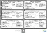
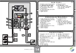
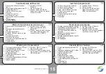
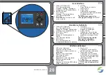
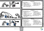
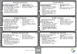
Type Label:
General Symbols
1. Ensure proper disposal
2. CE-mark
Safety Symbols
3. Read
documentation!
4.
aJ+Y
5.
aJ2;"Y
6.
W
ait for 5 Minutes before opening!
Bottom of Inverter:
7
. DC connection area
8. Ethernet / RS485
9.
ah
10. Digital I/O connection
11. AC-plug
12.
P
E-connections
Periodic Inspection:
Check if all markings and safety
symbols are clearly visible on the
inverter. Replace if necessary.
`% )&=
AC
7
11
9
8
10
12
12
TM
www
.sam
ilpo
wer.
com
PV
Grid-
tied
Inverte
r
T07
132
800
1
S/N:
Ro
H
S
Sola
rLak
e 700
0
-
TL P
M
VDC,m
ax:
100
0 V
VDC MP
P
,
:
380
- 80
0 V
IDC,m
ax:
2 x
A
11.5
VAC,r
:
230
/400
V
PAC,r
:
700
0 W
S
:
max
700
0 VA
f
:
AC,
r
50 /
60 H
z
IAC,m
ax:
10 A
cos
( ):
-0.8.
..
+0.8
1
...
Protect
ive
Class:
I
Ingre
ss
Protec
tion
:
IP6
5
Com
munication
Interfac
e:
IDC,sc
:
2 x
A
13
AC
DC
5 m
in.
1
2
3
6
4
5
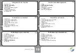
Typenschild:
Allgemeine Symbole
1.
V
orschriftsgemäß entsorgen
2. CE-Zeichen
Sicherheits
z
eichen
3. Installationsanleitung
lesen!
4.
a K``J;n>">
Spannung!
5.
aJog)Pn">Y
6.
V
or dem Öffnen 5 Minuten
w
arten!
Unterseite des
Wechselrichters:
7
. DC-Anschlussbereich
8. Ethernet / RS485
9.
W
Lan-Antenne
10. Digitale Ein- und Ausgänge
11. AC-Stecker
12.
P
E-Anschlüsse
Regelmäßige Überprüfung:
P
rüfen Sie ob alle Markierungen
und Sicherheits
z
eichen auf dem
W
echselrichter deutlich lesbar sind.
Erset
z
en Sie fehlende Markierungen.
Hinweise und Symbole auf dem Wechselrichter
EN
DE
FR
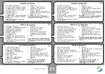
Plaque signalétique :
Symboles générau
x
1. Élimination conforme au
x
prescriptions
2. Marquage
CE
Marques de sécurité
3. Lecture impérative des instructions
d’installation
4.
d<KA22<<`AJ
dangereuse !
5.
!J;")pY
6.
P
atiente
z
5 minutes avant de
procéder à l’ouverture !
Dessous de l’onduleur :
7
. Zone de raccordement DC
8. Ethernet / RS485
9. Antenne
W
i-Fi
10. Entrées et sorties numériques
11. Connecteur AC
12. Raccords
P
E
Contrôle régulier :
Contrôle
z
si l’ensemble des
marquages et des marques de sécurité
)
lisibles. Remplace
z
les marquages si
nécessaire.
;)'% )


